140
CQM1 Memory Area Functions Section 3-1
3-1-5 HR Area
These bits retain their ON/OFF status even after the CQM1 power supply has
been turned off or when operation begins or stops. They are used in the same
way as work bits.
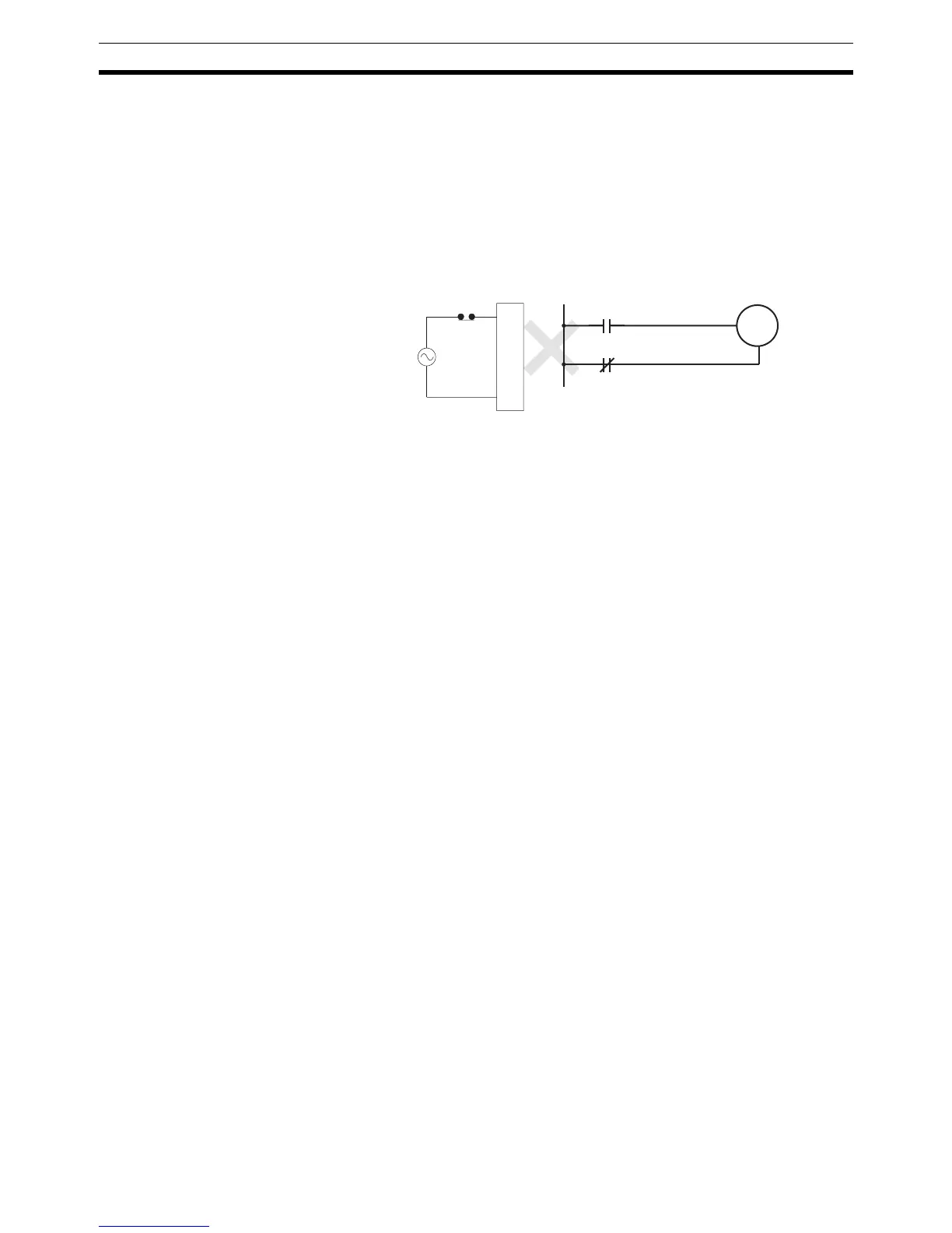
!Caution Never use an input bit in a NC condition on the reset (R) for KEEP(11) when
the input device uses an AC power supply (see diagram below). The delay in
shutting down the PC’s DC power supply relative to the AC power supply to
the input device can cause the designate bit of KEEP(11) to be reset.
3-1-6 AR Area
These bits mainly serve as flags related to CQM1 operation. For details on the
various bit functions, refer to relevant sections in this manual or to Appendix C
Memory Areas.
With the exception of AR 23 (Power-off Counter), the status of AR words and
bits is refreshed each cycle. (AR 23 is refreshed only for power interruptions.)
3-1-7 LR Area
When the CQM1 is linked one to one with another CQM1, these bits are used
to share data. For details, refer to page 102.
LR bits can be used as work bits when not used for data links.
3-1-8 Timer/Counter Area
This area is used to manage timers and counters created with TIM, TIMH(15),
CNT, and CNTR(12). The same numbers are used for both timers and
counters and each number can be used only once in the user program. Do not
use the same TC number twice even for different instructions.
TC number are used to create timers and counters, as well as to access Com-
pletion Flags and present values (PVs). If a TC number is designated for word
data, it will access the present value (PV); if it is used for bit data, it access the
Completion Flag for the timer/counter.
The Completion Flag turns ON when the PV of the timer/counter that is being
used goes to 0.
Refer to instructions beginning on page 212 for details on timers and
counters.
Note 1. TC numbers 000 through 015 and interrupt processing should be used for
TIMH(15) whenever the cycle time is longer than 10 ms. Using other timer/
counter numbers or not using interrupt processing will lead to inaccuracy
in the high-speed timers. Interrupt processing can be set in DM 6629 of the
PC Setup.
2. When the input condition turns OFF for TIM or TIMH(15), the PV is reset
and returns to the set value. The PV is also reset at the beginning of pro-
gram execution or when the interlock condition goes OFF in a interlocked
program section (IL–ILC). The PV for CNT or CNTR(12) is not reset like
KEEP
HR0000
B
A
AC
Set
Reset
Input Unit
A

 Loading...


