173
Basic Ladder Diagrams Section 4-3
There are two means of programming branching programs to preserve the
execution condition. One is to use TR bits; the other, to use interlocks (IL(02)/
IL(03)).
TR Bits The TR area provides eight bits, TR 0 through TR 7, that can be used to tem-
porarily preserve execution conditions. If a TR bit is placed at a branching
point, the current execution condition will be stored at the designated TR bit.
When returning to the branching point, the TR bit restores the execution sta-
tus that was saved when the branching point was first reached in program
execution.
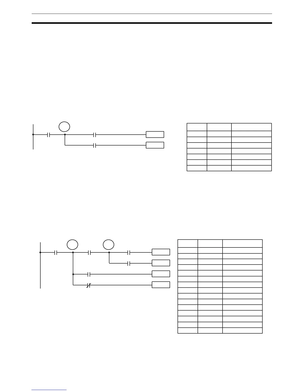
The previous diagram B can be written as shown below to ensure correct exe-
cution. In mnemonic code, the execution condition is stored at the branching
point using the TR bit as the operand of the OUTPUT instruction. This execu-
tion condition is then restored after executing the right-hand instruction by
using the same TR bit as the operand of a LOAD instruction
In terms of actual instructions the above diagram would be as follows: The
status of IR 00000 is loaded (a LOAD instruction) to establish the initial execu-
tion condition. This execution condition is then output using an OUTPUT
instruction to TR 0 to store the execution condition at the branching point. The
execution condition is then ANDed with the status of IR 00001 and instruction
1 is executed accordingly. The execution condition that was stored at the
branching point is then re-loaded (a LOAD instruction with TR 0 as the oper-
and), this is ANDed with the status of IR 00002, and instruction 2 is executed
accordingly.
The following example shows an application using two TR bits.
In this example, TR 0 and TR 1 are used to store the execution conditions at
the branching points. After executing instruction 1, the execution condition
stored in TR 1 is loaded for an AND with the status IR 00003. The execution
condition stored in TR 0 is loaded twice, the first time for an AND with the sta-
Instruction 1
00002
00000
Instruction 2
Diagram B: Corrected Using a TR bit
00001
TR 0
Address Instruction Operands
00000 LD 00000
00001 OUT TR 0
00002 AND 00001
00003 Instruction 1
00004 LD TR 0
00005 AND 00002
00006 Instruction 2
Instruction 1
00003
00000
00002
TR 1
00005
TR 0
00001
00004
Instruction 2
Instruction 3
Instruction 4
Address Instruction Operands
00000 LD 00000
00001 OUT TR 0
00002 AND 00001
00003 OUT TR 1
00004 AND 00002
00005 Instruction 1
00006 LD TR 1
00007 AND 00003
00008 Instruction 2
00009 LD TR 0
00010 AND 00004
00011 Instruction 3
00012 LD TR 0
00013 AND NOT 00005
00014 Instruction 4

 Loading...


