383
Host Link Commands Section 6-3
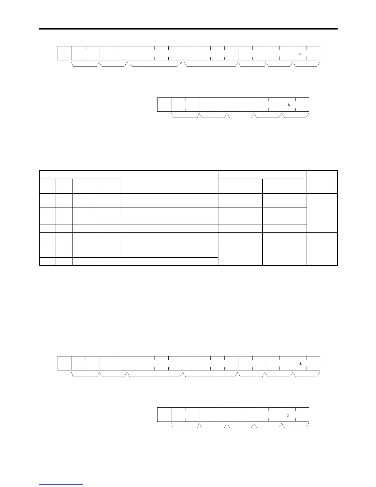
Command Format
Response Format An end code of 00 indicates normal completion.
Parameters Name, Word address, Bit (Command)
In “Name,” specify the area (i.e., IR, SR, LR, HR, AR, or TC) that is to be
forced set. Specify the name in four characters. In “Word address,” specify the
address of the word, and in “Bit” the number of the bit that is to be forced set.
Note The area specified under “Name” must be in four characters. Add spaces after
the data area name if it is shorter than four characters.
6-3-25 FORCED RESET –– KR
Force resets a bit in the IR, SR, LR, HR, AR, or TC area. Just one bit can be
force reset at a time.
Once a bit has been forced set or reset, that status will be retained until a
FORCED SET/RESET CANCEL (KC) command or the next FORCED SET/
RESET command is transmitted.
Command Format
Response Format An end code of 00 indicates normal completion.
@ KSx 10
0
x 10
1
x 10
3
x 10
2
x 10
1
x 10
0
x 10
1
x 10
0
↵
OP1 OP2 OP3 OP4
Node no. Header
code
TerminatorFCS
Name Word
address
Bit
@ KS
x 10
0
x 10
1
x 16
1
x 16
0
↵
Node no. Header
code
TerminatorFCSEnd code
Name Classification Word address setting range Bit
OP1 OP2 OP3 OP4 CQM1 PCs CPM1/ CPM1A/
SRM1 PCs
C I O (Space) IR or SR 0000 to 0252 0000 to 0019
0200 to 0252
00 to 15
(decimal)
L R (Space) (Space) LR 0000 to 0063 0000 to 0015
H R (Space) (Space) HR 0000 to 0099 0000 to 0019
A R (Space) (Space) AR 0000 to 0027 0000 to 0015
T I M (Space) Completion Flag (timer) 0000 to 0511 0000 to 0127 Always 00
T I M H Completion Flag (high-speed timer)
C N T (Space) Completion Flag (counter)
C N T R Completion Flag (reversible counter)
@ KRx 10
0
x 10
1
x 10
3
x 10
2
x 10
1
x 10
0
x 10
1
x 10
0
↵
OP1 OP2 OP3 OP4
Node no. Header
code
TerminatorFCS
Name Word
address
Bit
@ KRx 10
0
x 10
1
x 16
1
x 16
0
↵
Node no. Header
code
TerminatorFCSEnd code

 Loading...