423
SRM1 Cycle Time and I/O Response Time Section 7-3
3. Change to processing will cause cycle times to change therefore the cal-
culated values and actual values (for cycle time) will no always match.
7-3-2 SRM1 Cycle Time
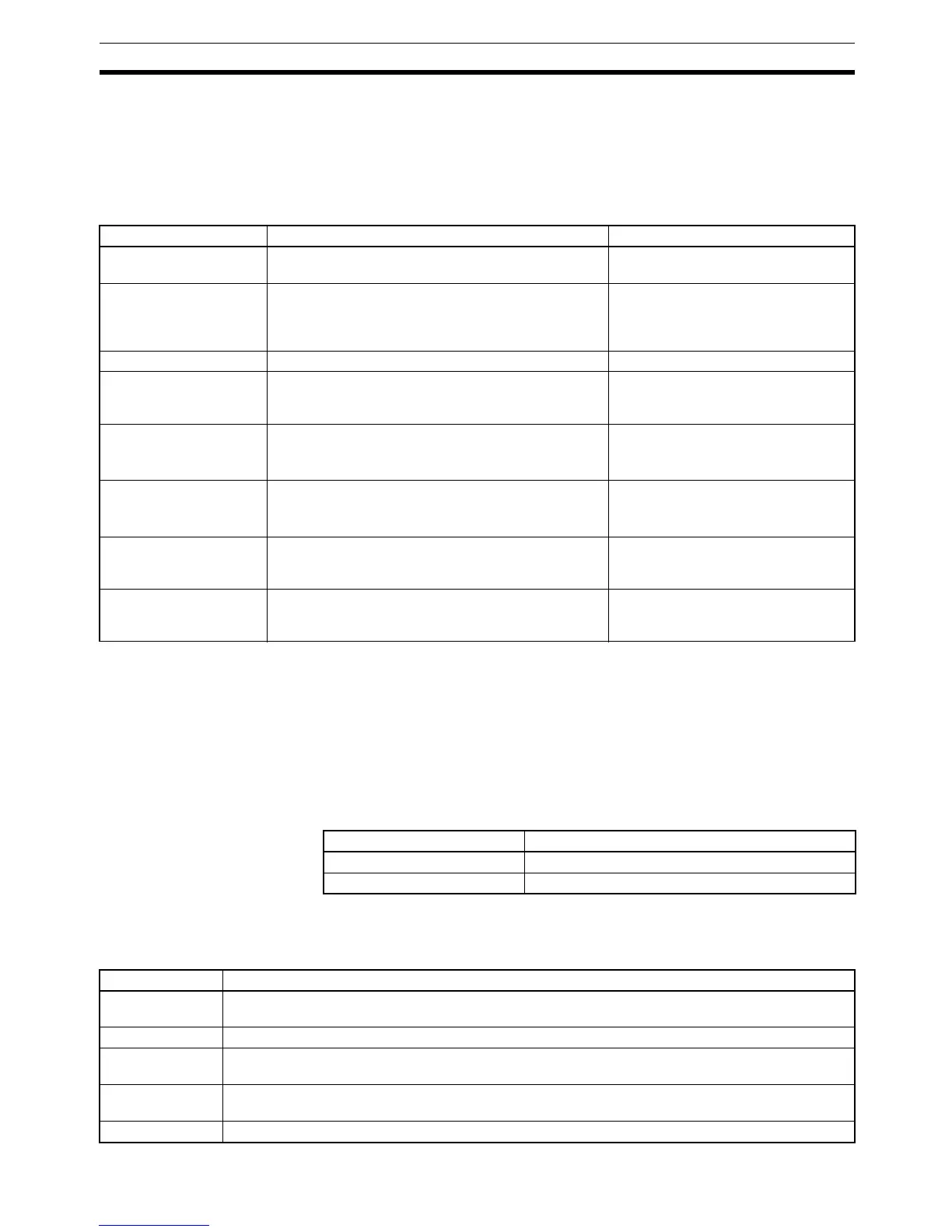
The processes involved in a single SRM1 cycle are shown in the following
table, and their respective processing times are explained.
Minimum Cycle Time In SRM1 PCs, CompoBus/S communications are started after the output
refresh is completed. As a result, when the overseeing time plus the RS-232C
port servicing time plus the peripheral port servicing time is shorter than the
CompoBus/S communications response time, processing is placed on stand-
by until CompoBus/S communications are completed.
The minimum cycle time therefore is the the CompoBus/S communications
response time plus the program execution time plus the input refresh time
plus the output refresh time. The CompoBus/S communications response
time depends on the maximum number of nodes set, as follows:
Cycle Time and
Operations
The effects of the cycle time on SRM1 operations are as shown below. When
a long cycle time is affecting operation, either reduce the cycle time or
improve responsiveness with interrupt programs.
Process Content Time requirements
Overseeing Setting cycle watchdog timer, UM check, refreshing
bits allocated to new functions, etc.
0.18 ms
CompoBus/S end wait Waiting for CompoBus/S processing to finish CompoBus/S communications
response time – Overseeing time –
RS-232C port servicing time – periph-
eral port servicing time
Input refreshing Input information is read to input bits. 0.02 ms
Program execution User program is executed.
Refer to 7-3-6 SRM1 Instruction Execution Times.
Total time for executing instructions.
(Varies according to content of user’s
program.)
Cycle time calculation Standby until set time, when minimum cycle time is
set in DM 6619 of PC Setup.
Calculation of cycle time.
Almost instantaneous, except for
standby processing.
Output refreshing Output information (results of executing program) is
written to output bits.
CompoBus/S communications are started.
0.05 ms
RS-232C port servicing Devices connected to RS-232C port serviced. 5% or less of cycle time, but always
between 0.55 and 131 ms (Set in
DM 6616)
Peripheral port servicing Devices connected to peripheral port serviced. 5% or less of cycle time, but always
between 0.55 and 131 ms (Set in
DM 6617)
Max. no. of nodes set CompoBus/S response time
32 0.8 ms
16 0.5 ms
Cycle time Operation conditions
10 ms or longer TIMH(15) may be inaccurate when TC 004 through TC 127 are used (operation will be normal for TC
000 through TC 003).
20 ms or longer Programming using the 0.02-second Clock Bit (SR 25401) may be inaccurate.
100 ms or longer TIM may be inaccurate. Programming using the 0.1-second Clock Bit (SR 25500) may be inaccurate.
A CYCLE TIME OVER error is generated (SR 25309 will turn ON). See note 1.
120 ms or longer The FALS 9F monitoring time SV is exceeded. A system error (FALS 9F) is generated, and operation
stops. See note 2.
200 ms or longer Programming using the 0.2-second Clock Bit (SR 25501) may be inaccurate.
 Loading...


