424
SRM1 Cycle Time and I/O Response Time Section 7-3
Note 1. The PC Setup (DM 6655) can be used to disable detection of CYCLE TIME
OVER error.
2. The cycle monitoring time can be changed in the PC Setup (DM 6618).
Cycle Time Example The following is an example of a cycle time calculation.
The operating conditions are assumed to be as follows:
User’s program:500 instructions (consists of only LD and OUT)
Cycle time: Variable (no minimum set)
RS-232C port: Not used.
Max. nodes: 32 (CompoBus/S communication response time = 0.8 ms)
Peripheral: 0.7 ms
The average processing time for a single instruction in the user’s program is
assumed to be 1.16
µs. The cycle times are as shown in the following table.
Note 1. The cycle time can be read from the PC via a Peripheral Device.
2. The maximum and current cycle time are stored in AR 14 and AR 15.
3. The cycle time can vary with actual operating conditions and will not nec-
essarily agree precisely with the calculated value.
4. When the peripheral port is used, there is no CompoBus/S end wait time
as it is always 0 or less.
5. CompoBus/S end wait time = 0.8 – 0.18 – 0 – 0 = 0.62 (CompoBus/S com-
munication response time – Overseeing – RS-232C port servicing time –
peripheral port servicing time.
7-3-3 I/O Response Time
The I/O response time is the time it takes after an input signal has been
received (i.e., after an input bit has turned ON) for the PC to check and pro-
cess the information and to output a control signal (i.e., to output the result of
the processing to an output bit).
CompoBus/S communications are started when the SRM1 input refresh fin-
ishes. The ON/OFF status is read from the Input Terminals during the input
refresh and the ON/OFF status is output to the Output Terminal during the
output refresh. Accordingly, the SRM1 I/O response time varies according to
the cycle time and CompoBus/S communications cycle status or I/O timing.
Example calculations of the I/O response time are provided next.
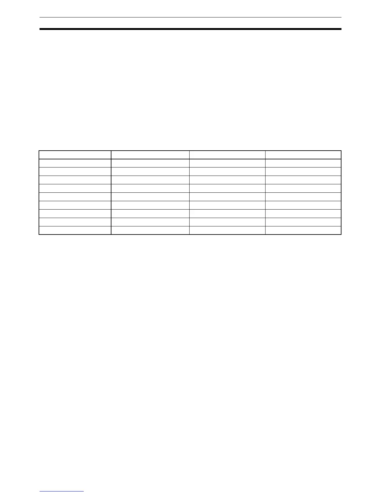
Process Calculation method Peripheral port used Peripheral port not used
1. Overseeing Fixed 0.18 ms 0.18 ms
2. CompoBus/S end wait See previous page. 0.00 ms 0.62 ms
3. Input refresh Fixed 0.02 ms 0.02 ms
4. Program execution 1.16 × 500 (µs) 0.8 ms 0.8 ms
5. Cycle time calculation Negligible 0.00 ms 0.00 ms
6. Output refresh 0.01 × 1 + 0.005 × 1 (µs) 0.05 ms 0.05 ms
7. RS-232C port servicing Not required 0.00 ms 0.00 ms
8. Peripheral port servicing 5% of cycle time 0.7 ms 0.00 ms
Cycle time (1) + (2) + (3) + ...+ (8) 1.75 ms 1.67 ms
 Loading...


