470
Memory Areas Appendix C
5. The contents of the HR area, LR area, Counter area, and read/write DM area are backed up by a
capacitor. The backup time varies with the ambient temperature, but at 25
°C, the capacitor will back
up memory for 20 days. If the power supply is off longer than the backup time, memory contents will
be cleared and AR1314 will turn ON. (This flag turns ON when data can no longer be retained by the
built-in capacitor.) Refer to 2-1-2 Characteristics in the CPM1 Operation Manual for a graph showing
the backup time vs. temperature.
SR Area
These bits mainly serve as flags related to CPM1/CPM1A operation or contain present and set values for vari-
ous functions. The functions of the SR area are explained in the following table.
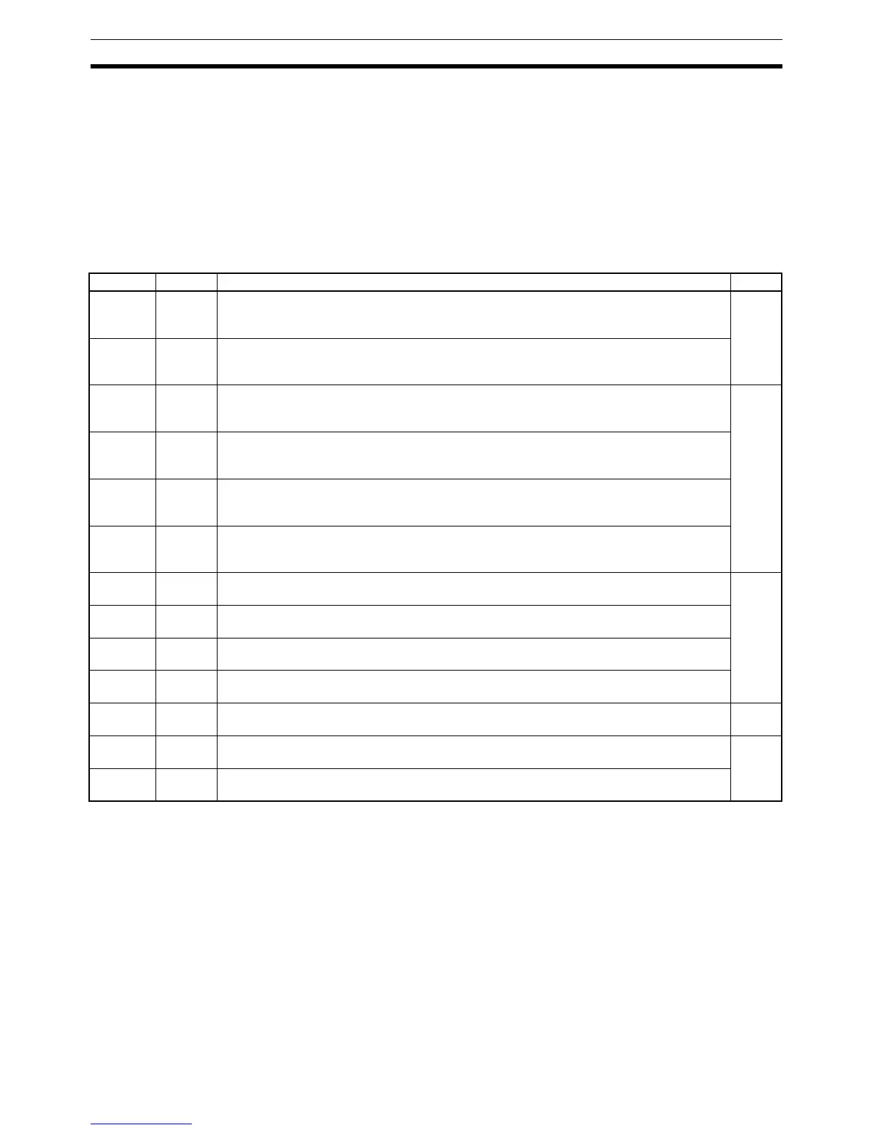
Word(s) Bit(s) Function Page
SR 232
to
SR 235
00 to 15 Macro Function Input Area
Contains the input operands for MCRO(99).
(Can be used as work bits when MCRO(99) is not used.)
130
SR 236
to
SR 239
00 to 15 Macro Function Output Area
Contains the output operands for MCRO(99).
(Can be used as work bits when MCRO(99) is not used.)
SR 240 00 to 15 Input Interrupt 0 Counter Mode SV
SV when input interrupt 0 is used in counter mode (4 digits hexadecimal).
(Can be used as work bits when input interrupt 0 is not used in counter mode.)
42
SR 241 00 to 15 Input Interrupt 1 Counter Mode SV
SV when input interrupt 1 is used in counter mode (4 digits hexadecimal).
(Can be used as work bits when input interrupt 1 is not used in counter mode.)
SR 242 00 to 15 Input Interrupt 2 Counter Mode SV
SV when input interrupt 2 is used in counter mode (4 digits hexadecimal).
(Can be used as work bits when input interrupt 2 is not used in counter mode.)
SR 243 00 to 15 Input Interrupt 3 Counter Mode SV
SV when input interrupt 3 is used in counter mode (4 digits hexadecimal).
(Can be used as work bits when input interrupt 3 is not used in counter mode.)
SR 244 00 to 15 Input Interrupt 0 Counter Mode PV Minus One
Counter PV–1 when input interrupt 0 is used in counter mode (4 digits hexadecimal).
42
SR 245 00 to 15 Input Interrupt 1 Counter Mode PV Minus One
Counter PV–1 when input interrupt 1 is used in counter mode (4 digits hexadecimal).
SR 246 00 to 15 Input Interrupt 2 Counter Mode PV Minus One
Counter PV–1 when input interrupt 2 is used in counter mode (4 digits hexadecimal).
SR 247 00 to 15 Input Interrupt 3 Counter Mode PV Minus One
Counter PV–1 when input interrupt 3 is used in counter mode (4 digits hexadecimal).
SR 248,
SR 249
00 to 15 High-speed Counter PV Area
(Can be used as work bits when the high-speed counter is not used.)
48
SR 250 00 to 15 Analog Volume Setting 0
Used to store the 4-digit BCD set value (0000 to 0200) from analog volume control 0.
131
SR 251 00 to 15 Analog Volume Setting 1
Used to store the 4-digit BCD set value (0000 to 0200) from analog volume control 1.

 Loading...


