473
Memory Areas Appendix C
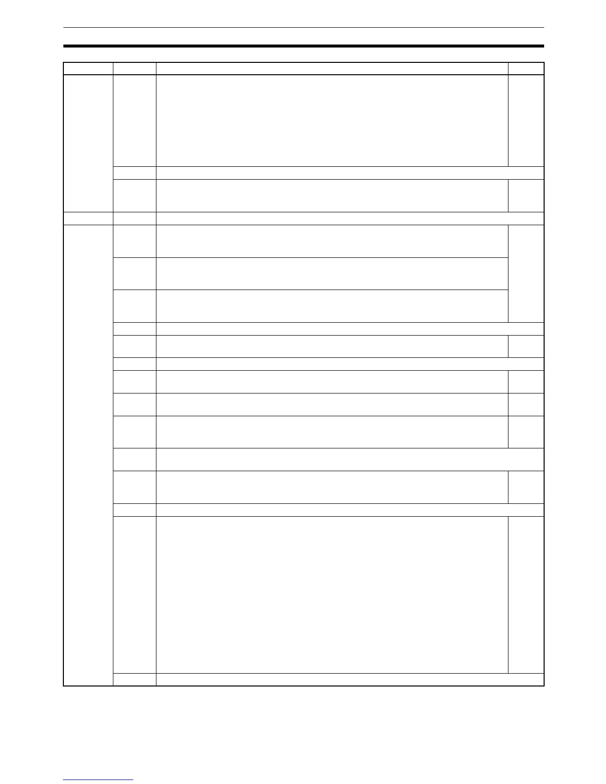
AR 11 00 to 07 High-speed Counter Range Comparison Flags
00 ON: Counter PV is within comparison range 1
01 ON: Counter PV is within comparison range 2
02 ON: Counter PV is within comparison range 3
03 ON: Counter PV is within comparison range 4
04 ON: Counter PV is within comparison range 5
05 ON: Counter PV is within comparison range 6
06 ON: Counter PV is within comparison range 7
07 ON: Counter PV is within comparison range 8
51
08 to 14 Not used.
15 Pulse Output Status
ON: Stopped.
OFF: Pulses being output.
---
AR 12 00 to 15 Not used.
AR 13 00 Power-up PC Setup Error Flag
Turns ON when there is an error in DM 6600 to DM 6614 (the part of the PC Setup area
that is read at power-up).
3
01 Start-up PC Setup Error Flag
Turns ON when there is an error in DM 6615 to DM 6644 (the part of the PC Setup area
that is read at the beginning of operation).
02 RUN PC Setup Error Flag
Turns ON when there is an error in DM 6645 to DM 6655 (the part of the PC Setup area
that is always read).
03, 04 Not used.
05 Long Cycle Time Flag
Turns ON if the actual cycle time is longer than the cycle time set in DM 6619.
---
06, 07 Not used.
08 Memory Area Specification Error Flag
Turns ON when a non-existent data area address is specified in the program.
---
09 Flash Memory Error Flag
Turns ON when there is an error in flash memory.
---
10 Read-only DM Error Flag (See note 3.)
Turns ON when a checksum error occurs in the read-only DM (DM 6144 to DM 6599)
and that area is initialized.
3
11 PC Setup Error Flag
Turns ON when a checksum error occurs in the PC Setup area.
12 Program Error Flag
Turns ON when a checksum error occurs in the program memory (UM) area, or when an
improper instruction is executed.
---
13 Not used.
14 Data Save Error Flag
Turns ON when power is turned on if data could not be saved with the built-in capacitor.
Data is saved in the following areas with the built-in capacitor:
DM area (Read/write-capable: DM 0000 to 0999 and DM 1022 to 1023)
HR area (HR 00 to 19)
Counter area (CNT 000 to 127)
SR area, word 252, bits 11, 12 (when PC Setup in DM 6601 is set to maintain status)
AR area, word 10 (power-off counter)
Operation mode (when PC Setup in DM 6600 is set to continue mode last used before
power failure)
If data could not be saved in the above areas:
The DM, error log, HR, counter, SR (word 252, bits 11 and 12), and AR (word 10) areas
will be cleared.
The operation mode will go into Program Mode.
(For details regarding the holding time, refer to the CPM1A Operation Manual.)
---
15 Not used.
Word(s) Bit(s) Function Page

 Loading...


