472
Memory Areas Appendix C
Note DM 6601 in the PC Setup can be set to maintain the previous status of the I/O Hold Bit (SR 25212) and
the I/O Hold Bit (SR 25212) when power is turned off. If power is left OFF for longer than the backup
time, however, status may be cleared. For details regarding the backup time, refer to the CPM1A or
CPM1 Operation Manual. Refer to 1-1-3 CPM1/CPM1A PC Setup Settings for details on the PC Setup.
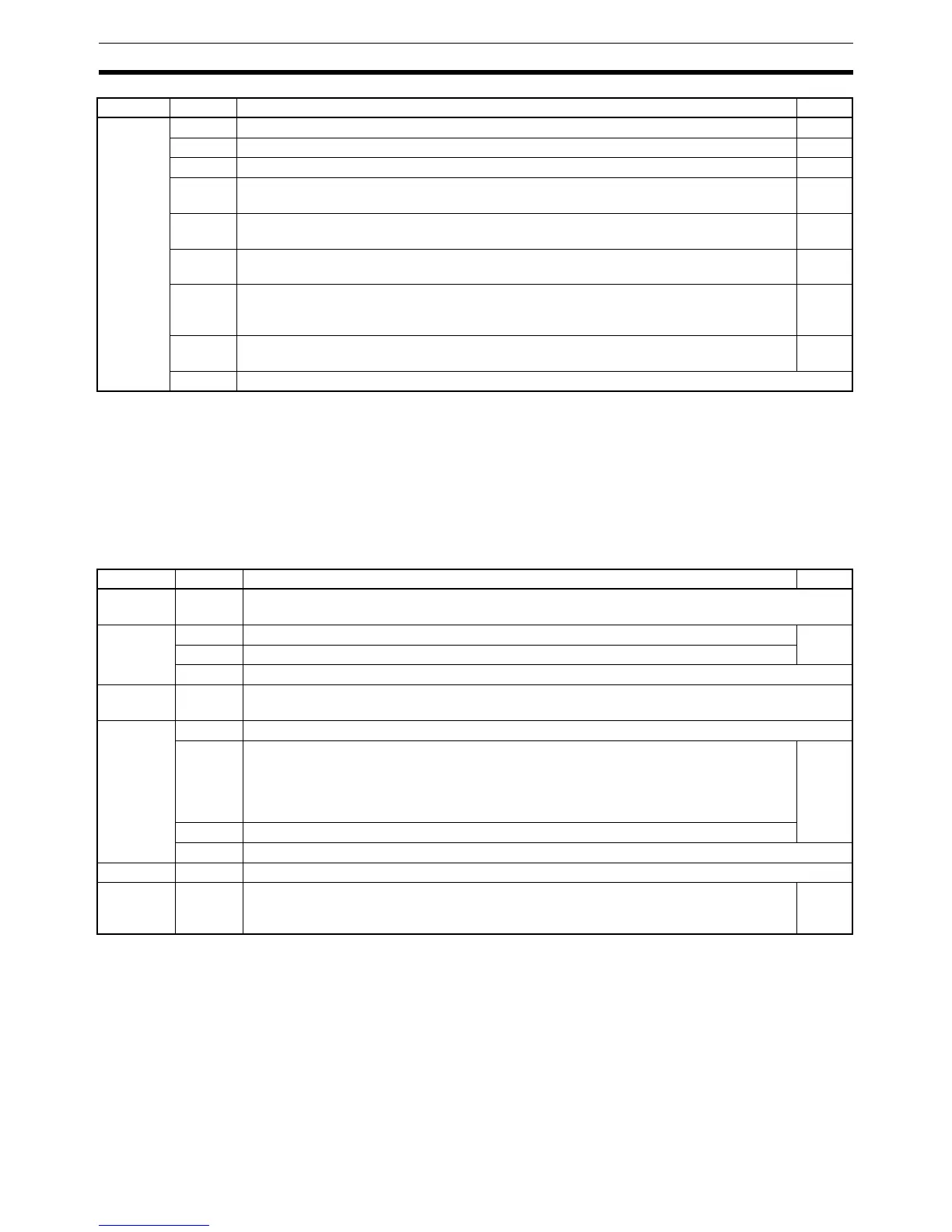
AR Area
These bits mainly serve as flags related to CPM1/CPM1A operation. These bits retain their status even after
the CPM1/CPM1A power supply has been turned off or when operation begins or stops.
SR 255 00 0.1-second clock pulse (0.05 second ON; 0.05 second OFF) ---
01 0.2-second clock pulse (0.1 second ON; 0.1 second OFF) ---
02 1.0-second clock pulse (0.5 second ON; 0.5 second OFF) ---
03 Instruction Execution Error (ER) Flag
Turns ON when an error occurs during execution of an instruction.
---
04 Carry (CY) Flag
Turns ON when there is a carry in the results of an instruction execution.
---
05 Greater Than (GR) Flag
Turns ON when the result of a comparison operation is “greater.”
---
06 Equals (EQ) Flag
Turns ON when the result of a comparison operation is “equal,” or when the result of an
instruction execution is 0.
---
07 Less Than (LE) Flag
Turns ON when the result of a comparison operation is “less.”
---
08 to 15 Not used.
Word(s) Bit(s) Function Page
AR 00,
AR 01
00 to 15 Not used.
AR 02 00 to 07 Not used. ---
08 to 11 Number of I/O Units Connected
12 to 15 Not used.
AR 03 to
AR 07
00 to 15 Not used.
AR 08 00 to 07 Not used.
08 to 11 Peripheral Device Error Code
0: Normal completion
1: Parity error
2: Frame error
3: Overrun error
101
12 Peripheral Device Error Flag
13 to 15 Not used.
AR 09 00 to 15 Not used.
AR 10 00 to 15 Power-off Counter (4 digits BCD)
This is the count of the number of times that the power has been turned off.
To clear the count, write “0000” from a peripheral device.
---
Word(s) Bit(s) Function Page

 Loading...


