48
CQM1 Interrupt Functions Section 1-5
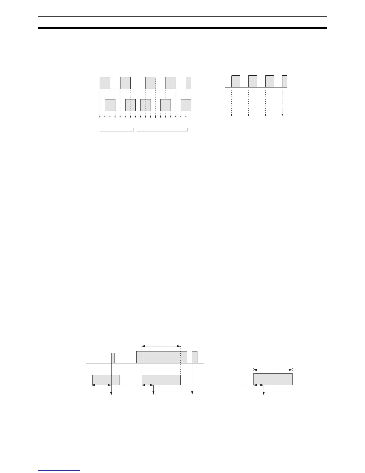
Incrementing mode: One single-phase pulse signal and a count reset signal
are used for inputs. The count is incremented according
to the single-phase signal.
Note One of the methods in the following section should always be used to reset
the counter when restarting it. The counter will be automatically reset when
program execution is started or stopped.
The following signal transitions are handled as forward (incrementing) pulses:
A-phase leading edge to B-phase leading edge to A-phase trailing edge to B-
phase trailing edge. The following signal transitions are handled as reverse
(decrementing) pulses: B-phase leading edge to A-phase leading edge to B-
phase trailing edge to A-phase trailing edge.
The count range is from –32,767 to 32,767 for Up/Down Mode, and from 0 to
65,535 for Incrementing Mode. Pulse signals can be counted at up to 2.5 kHz
in Up/Down Mode, and up to 5.0 kHz in Incrementing Mode.
The Up/Down Mode always uses a 4X phase-difference input. The number of
counts for each encoder revolution would be 4 times the resolution of the
counter. Select the encoder based on the countable ranges.
Reset Methods
Either of the two methods described below may be selected for resetting the
PV of the count (i.e., setting it to 0).
Z-phase signal + software reset: The PV is reset when the Z-phase signal
(reset input) turns ON after the High-speed
Counter 0 Reset Bit (SR 25200) is turned
ON.
Software reset: The PV is reset when the High-speed Counter 0 Reset Bit
(SR 25200) is turned ON.
Note The High-speed Counter 0 Reset Bit (SR 25200) is refreshed once every
cycle, so in order for it to be read reliably it must be ON for at least one cycle.
1234567876543210–1–2
1 2 3 4
A-phase
B-phase
Up/Down Mode
Count
Incremented Decremented
Count
Pulse
input
Incrementing Mode
Incremented only
SR25200
Z-phase
(reset input)
Z-phase signal + software reset
1 or more cycles
1 or more cycles
Reset by interrupt.
Within 1 cycle
Reset by cycle. Not reset. Reset by cycle.
Within 1 cycle
1 or more cycles
Software reset
SR25200

 Loading...


