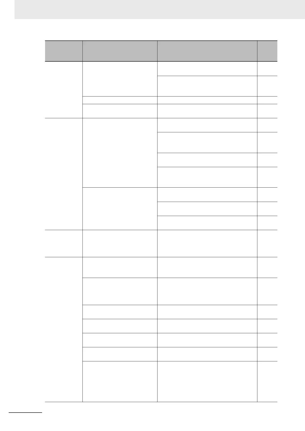
Symptom Possible cause Remedy
Refer-
ence
page
The output fre-
quency is un-
stable.
The parameter settings are inap-
propriate.
Change the output frequency value slightly
away from the power supply frequency.
page
5-27
Change 1st Output Current Fluctuation Damp-
ing Gain (H80) and 2nd Output Current Fluctu-
ation Damping Gain (A41).
page
7-144
The load changes significantly.
Increase the motor/inverter capacity. -
The power supply voltage fluctu-
ates.
Take measure to reduce the fluctuation.
-
The torque is
insuf
ficient.
The parameter settings are inap-
propriate. (During acceleration/
constant speed)
Increase 1st Manual Torque Boost V
oltage
(F09)/2nd Manual Torque Boost Voltage (A05).
page
5-73
Set the 1st Torque Boost Function Selection
(E112) and 2nd Torque Boost Function Selec-
tion (E1
13) to “1: Automatic torque boost.”
page
5-73
Decrease the Carrier Frequency (F26). page
7-113
Set the 1st Drive Control Selection (F42)/2nd
Drive Control Selection (A14) to “5: IM Vector
control without speed sensor.”
page
6-
16
The parameter settings are inap-
propriate. (During deceleration)
Increase the value set in the deceleration time
(F08/E11/E13/E15).
page
5-39
Set 1st AVR Function Selection (E122)/2nd
AVR Function Selection (E123) to OFF.
page
7-121
Use braking resistors or regenerative braking
units.
-
Operator com-
munications er-
ror (Er2) occur-
red.
Broken wiring between the opera-
tor and the inverter unit.
Check the connection between the digital op-
erator and the inverter unit.
-
The operation/
setting via Mod-
bus communi-
cation is not
possible.
1st RUN Command Selection
(F02)/2nd RUN Command Selec-
tion (E102) are incorrect.
Set 1st RUN Command Selection (F02)/2nd
RUN Command Selection (E102) to “4.
RS-485 communication (terminal block).”
page
5-
25
1st Frequency Reference Selec-
tion (F01)/2nd Frequency Refer-
ence Selection (C30) are incor-
rect.
Set 1st Frequency Reference Selection
(F01)/2nd Frequency Reference Selection
(C30) to “14. RS-485 communication (terminal
block).”
page
5-27
The communications speed set-
ting is incorrect.
Set a correct communications speed in the
RS-485 Communication Baud Rate (y14).
page
8-5
The unit number setting is incor-
rect or overlaps.
Set a correct station number in the RS-485
Communication Station No. Selection (y11).
page
8-
5
The communications parity setting
is incorrect.
Set a correct parity type in the RS-485 Com-
munication Parity Bit Selection (y16).
page
8-5
The wiring is incorrect. Connect the wiring correctly to the terminal
SP/SN on the control circuit terminal block.
page
8-4
The address is incorrect.
• Check that the coil or register address set-
ting is correct, which is 1 less than the coil
or register No.
• If the Modbus mapping function is in use,
check if the function settings are correct
and, if necessary, make corrections.
page
8-11
page
8-23
9 Troubleshooting
9-34
M1 Series Standard Type User's Manual (I669)
 Loading...