5-78
5-16 User Parameters
5
Operating Functions
• Use these parameters to set the electronic gear.
• The electronic gear can be used for the following:
• To set the amount of Servomotor rotation or movement per input command pulse.
• To increase the nominal command pulse frequency by using a multiplier when the desired
Servomotor speed cannot be achieved due to the limited pulse oscillation capability of the host
controller.
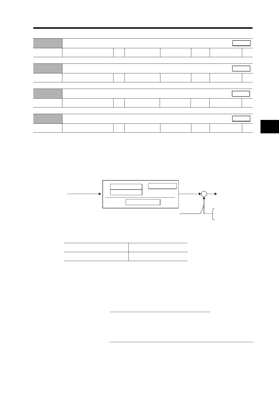
• Electronic Gear Block Diagram
*1. Numerator 1 or Numerator 2 is selected using the Electronic Gear Switch Input (GESEL: CN1 pin
28).
• The gear ratio is set using the following equations.
If the numerator equals 0, the following value is set automatically.
Numerator ((Pn48 or Pn49) × 2
Pn4A
) = Encoder resolution
In this case, the number of command pulses per revolution can be set in Pn4B.
If the numerator does not equal 0, the gear ratio is as follows:
The upper limit of the calculated numerator ((Pn48 or Pn49) × 2
Pn4A
) is 4,194,304/ (Pn4D setting
+ 1).
Pn48
Electronic Gear Ratio Numerator 1
Setting range 0 to 10000 Unit --- Default setting 0
Power OFF→ON
---
Pn49
Electronic Gear Ratio Numerator 2
Setting range 0 to 10000 Unit --- Default setting 0
Power OFF→ON
---
Pn4A
Electronic Gear Ratio Numerator Exponent
Setting range 0 to 17 Unit --- Default setting 0
Power OFF→ON
---
Pn4B
Electronic Gear Ratio Denominator
Setting range 0 to 10000 Unit --- Default setting 10000
Power OFF→ON
---
GESEL input open Numerator 1 (Pn48) selected.
GESEL input connected to COM Numerator 2 (Pn49) selected.
× 2
*1
*1
F
f
+
−
Command pulses
Numerator 1 (Pn48)
Numerator 2 (Pn49)
Exponent (Pn4A)
Denominator (Pn4B)
Internal
command
Feedback
pulses
(resolution)
To deviation
counter
10,000 pulses/re
or
2
17
ulses/rev
Electronic gear ratio =
Encoder resolution
Number of command pulses per Servomotor rotation (Pn4B)
Electronic gear ratio =
Electronic gear ratio numerator (Pn48 or Pn49) × 2
Electronic gear ratio numerator exponent (Pn4A)
Electronic gear ratio denominator (Pn4B)
 Loading...


