9-19
9-2 Parameter Tables
9
Appendix
30
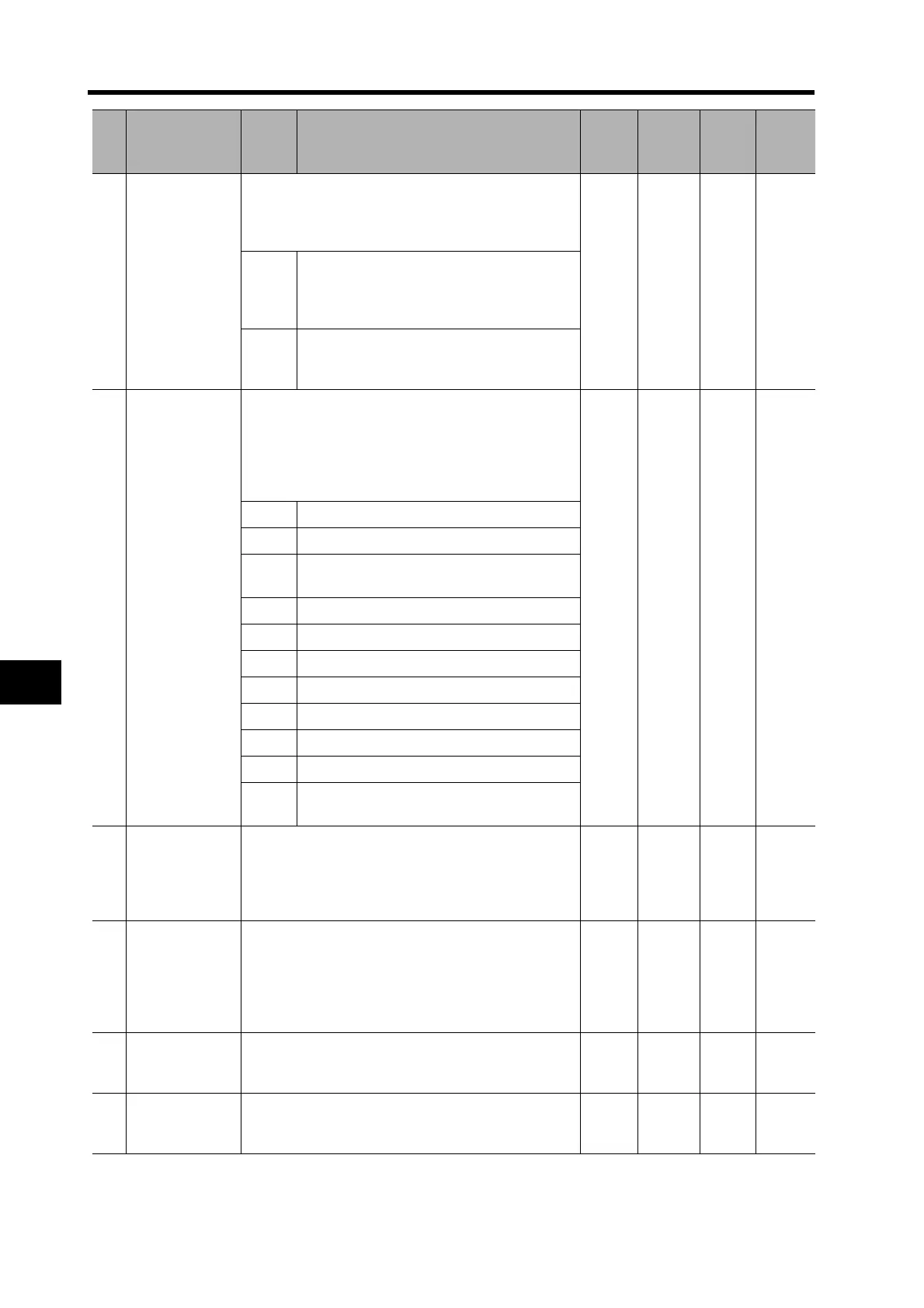
Gain Switching
Input Operating
Mode Selection
Enable or disable gain switching.
If gain switching is enabled, the setting of the Control
Gain Switch Setting (Pn31) is used as the condition
for switching between gain 1 and gain 2.
1 --- 0 to 1 ---
0
Disabled. The gain set in Pn10 to Pn14 is
used, and the Gain Switching Input (GSEL)
will be used to switch between PI operation
and P operation.
1
Enabled. The gain will be switched between
gain 1 (Pn10 to Pn14) and gain 2 (Pn18 to
Pn1C).
31
Control Gain
Switch 1 Setting
Select the condition for switching between gain 1 and
gain 2. The details depend on the control mode.
If a composite mode is set, the setting of this param-
eter is valid when the first control mode is used. The
Gain Switching Input Operating Mode Selection
(Pn30) must be set to 1 (enabled).
0 --- 0 to 10 ---
0 Always gain 1
1 Always gain 2
2
Switching using Gain Switching Input
(GSEL)
3 Amount of change in torque command
4 Always gain 1
5 Command speed
6 Amount of position deviation
7 Command pulses received
8 Positioning Completed Signal (INP) OFF
9 Actual Servomotor speed
10
Combination of command pulse input and
speed
32
Gain Switch 1
Time
This parameter is enabled when the Control Gain
Switch 1 Setting (Pn31) is 3 to 10. Set the delay time
from the moment the condition set in the Control Gain
Switch 1 Setting (Pn31) is not met until returning to
gain 1.
30 166 μs
0 to
10000
---
33
Gain Switch 1
Level Setting
This parameter is enabled when the Control Gain
Switch 1 Setting (Pn31) is 3 to 6, 9, or 10. Set the
judgment level for switching between gain 1 and gain
2.
The unit for the setting depends on the condition set
in the Control Gain Switch 1 Setting (Pn31).
600 ---
0 to
20000
---
34
Gain Switch 1
Hysteresis
Setting
Set the hysteresis width above and below the judg-
ment level set in the Gain Switch 1 Level Setting
(Pn33).
50 ---
0 to
20000
---
35
Position Loop
Gain Switching
Time
When switching between gain 1 and gain 2 is en-
abled, set the phased switching time only for the posi-
tion loop gain at gain switching.
20 166 μs
0 to
10000
---
Pn
No.
Parameter
name
Setting Explanation
Default
setting
Unit
Setting
range
Power
OFF→
ON

 Loading...

