Connection
ZFX-C User’s Manual
6
PARALLEL INTERFACE
157
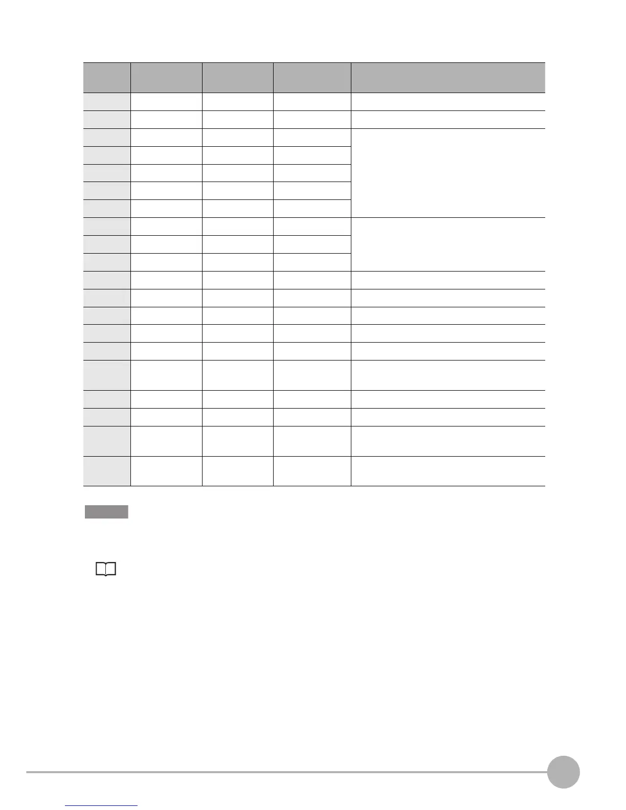
The pin assignment is as follows. Wire only required pins.
.
Be sure to wire COMIN and COMOUT as well as the I/O signals.
For details on wiring, see the internal circuit diagrams.
Internal Specifications p.160
Pin No. Signal name Wire color
(ZFX-VP)
Signal direction Function
1 RESET Brown Input Restarts the ZFX.
2 TRIG Red Input Measurement trigger signal input
3 DI0 Orange Input Command parameter
4 DI1 Yellow Input
5 DI2 Green Input
6 DI3 Blue Input
7 DI4 Purple Input
8 DI5 Gray Input Command input
9 DI6 White Input
10 DI7 Black Input
11 DI8 Brown Input Parallel command confirmation signal
12 DSA Red Input Data send request signal input
13 OR Orange Output Overall judgment output
14 ERROR Yellow Output ON when an error occurs
15 RUN Green Output ON while in the RUN mode
16 ENABLE Blue Output ON when measurement trigger signal can be
input
17 GATE Purple Output ON for the preset output time
18 DO15 Gray Output Data output
19 COMIN White - Common for input signals, STGOUT0 and
STGOUT1
20 COMOUT Black - Common for OR, ERROR, RUN, ENABLE,
GATE, DO15 signals