Timing Charts
172
ZFX-C User’s Manual
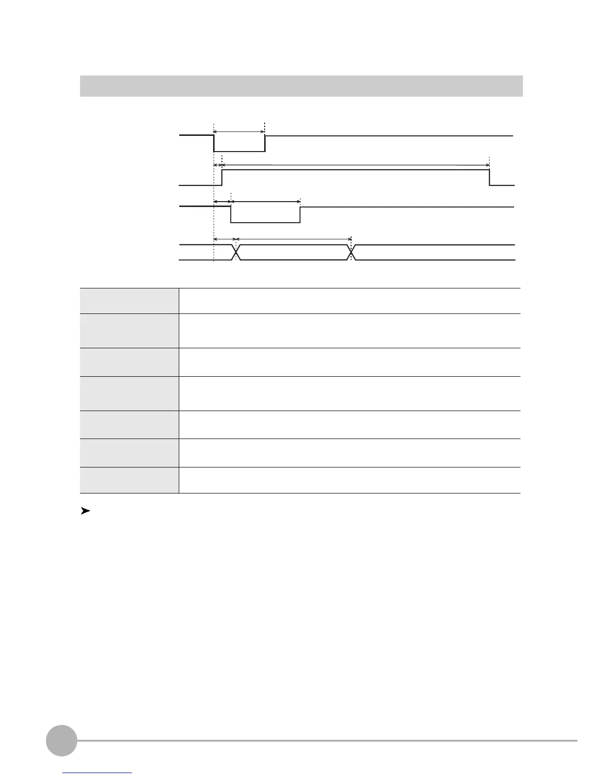
Signal Operation in terms of Measurement
Trigger Input
Explanation of operation
(1) When two cameras are connected, delay the shutter open/close timing of cameras 0 and 1 by the trigger
delay time (T4) to prevent mutual interface.
(2) The STGOUT signal is used to output the strobe firing trigger to the strobe device connected to the
Controller. After the shutter opens, the STGOUT signal is output after the STGOUT delay time (T6) has
elapsed, and the strobe fires. The ON/OFF polarity of the STGOUT signal can be changed.
T1:
Trigger input time
Set to ON for at least 0.5 ms.
T2:
ENABLE output
response time
This is the time after the trigger is input until the ENABLE signal turns OFF. 0.5 ms or less
T3:
Measurement time
This time is "image input" + "measurement". This time can be changed to only "image
input" or "image input" + "measurement" + "display".
T4:
Trigger delay time
This is the time after trigger input until the camera's shutter is opened (max. 65.535 ms).
This time can be changed for each camera. This time can be set only when the ZFX-C2_
is used.
T5:
Shutter time
This is the time that the image is captured (max. 2 ms).
This time can be changed by the shutter speed setting for each camera.
T6:
Strobe delay time
This is the time after trigger input until the Controller outputs the STGOUT signal (max.
65.535 ms). This time can be changed for each camera.
T7:
Strobe pulse width
This is the strobe trigger output time (max. 65.535 ms). This time can be changed for
each camera.