Connection
ZFX-C User’s Manual
6
PARALLEL INTERFACE
159
*1: Use the STGOUT0 or STGOUT1 signal when you want to connect a strobe device to the ZFX.
*2: Do not connect any signals in the case of the ZFX-C10H/C15H/C10/C15.
Be sure to wire COMOUT as well as the I/O signals.
For details on wiring, see the internal circuit diagrams.
Internal Specifications p.160
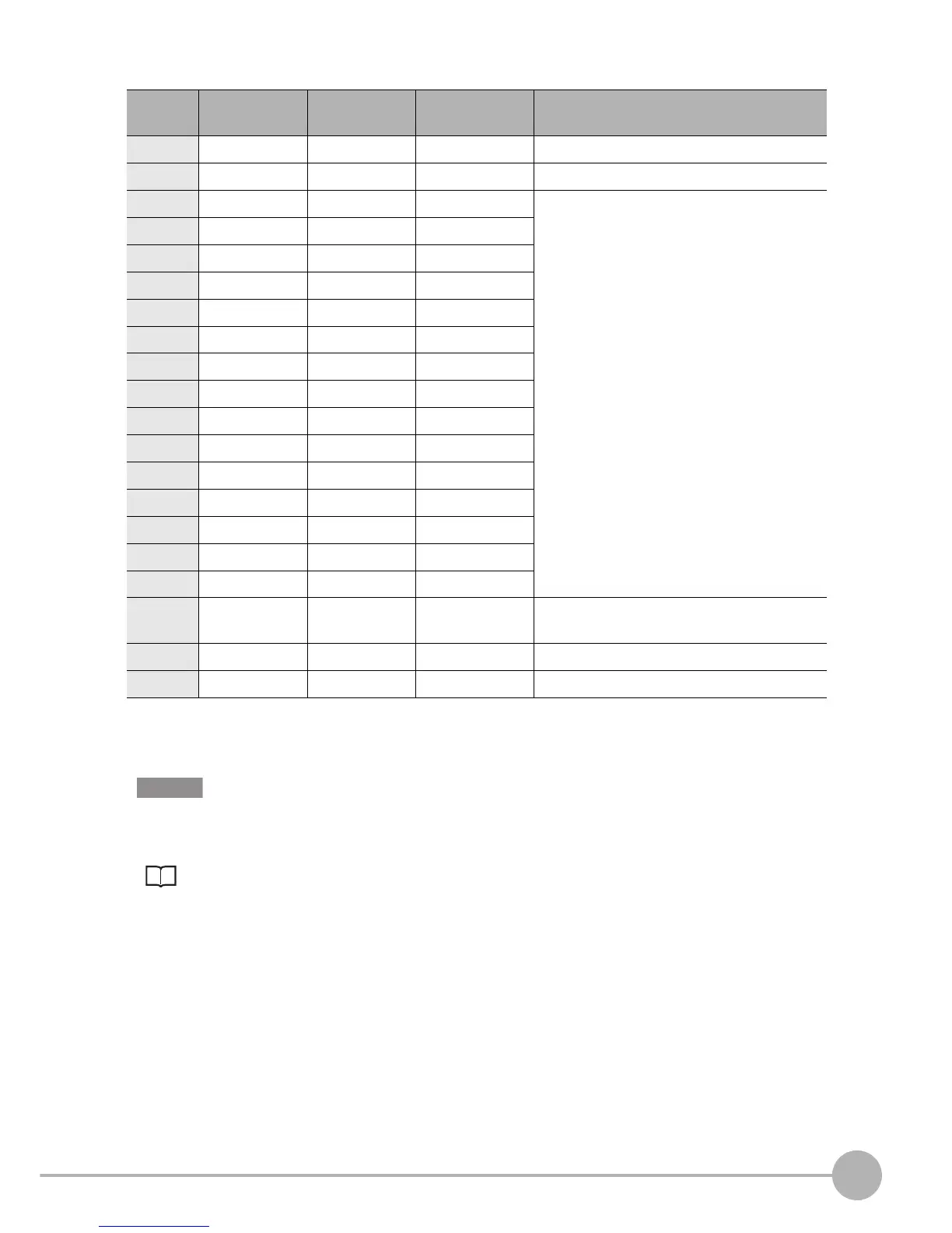
Pin No. Signal name Wire color
(ZFX-VP)
Signal direction Function
1 STGOUT0 Brown Output Strobe trigger 0 output (for camera 0) *1
2 STGOUT1 Red Output Strobe trigger 1 output (for camera 1) *1 *2
3 DO0 Orange Output Data output
4 DO1 Yellow Output
5 DO2 Green Output
6 DO3 Blue Output
7 DO4 Purple Output
8 DO5 Gray Output
9 DO6 White Output
10 DO7 Black Output
11 DO8 Brown Output
12 DO9 Red Output
13 DO10 Orange Output
14 DO11 Yellow Output
15 DO12 Green Output
16 DO13 Blue Output
17 DO14 Purple Output
18 COMOUT Gray - Common for STGOUT0, STGOUT1, and DO0
to DO6 signals
19 (OPEN) White - (Leave open.)
20 COMOUT Black - Common for DO7 to DO14 signals
Important