123
Step 5. Close the cover.
Step 6. Fire the laser.
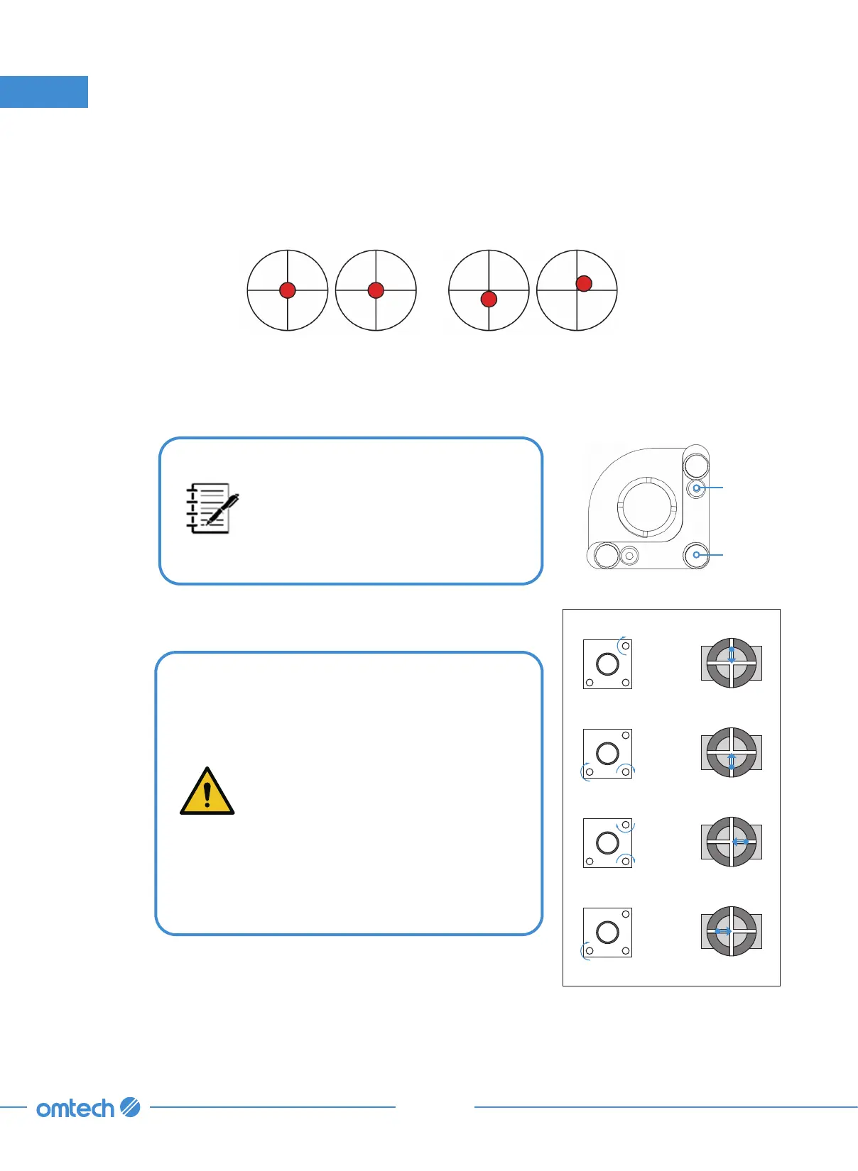
Step 7. Check that the burnt hole on the tape is at its center.
8. Maintenance
These marks are OK. These marks require adjustment.
If not,
Step 8. Cut the power to your laser and open the rear access door to expose Mirror 1 as shown.
If the last burnt hole is way
off-mark, you may need to loosen
the mounting bolts of Mirror 1 to
slide it into a better position before
fine-tuning the setscrews.
Setscrews
Mounting
Bolts
Lower Beam
Raise Beam
Move Beam Left
Lower Beam Right
Step 9. Carefully turn the setscrews on Mirror 1 to adjust the
angle and position of Mirror 1.
•
Each screw adjusts a different
position or angle.
•
Keep track of which screw you
are adjusting and the direction of
adjustment.
•
Do not turn the screw more than
¼
turn at a time and, especially
at first, test the position of the
laser after each adjustment so
that you learn the effect of each
change.