Parker Hannifin S.p.A. Divisione S.B.C. user’s manual TWIN-N and SPD-N
187
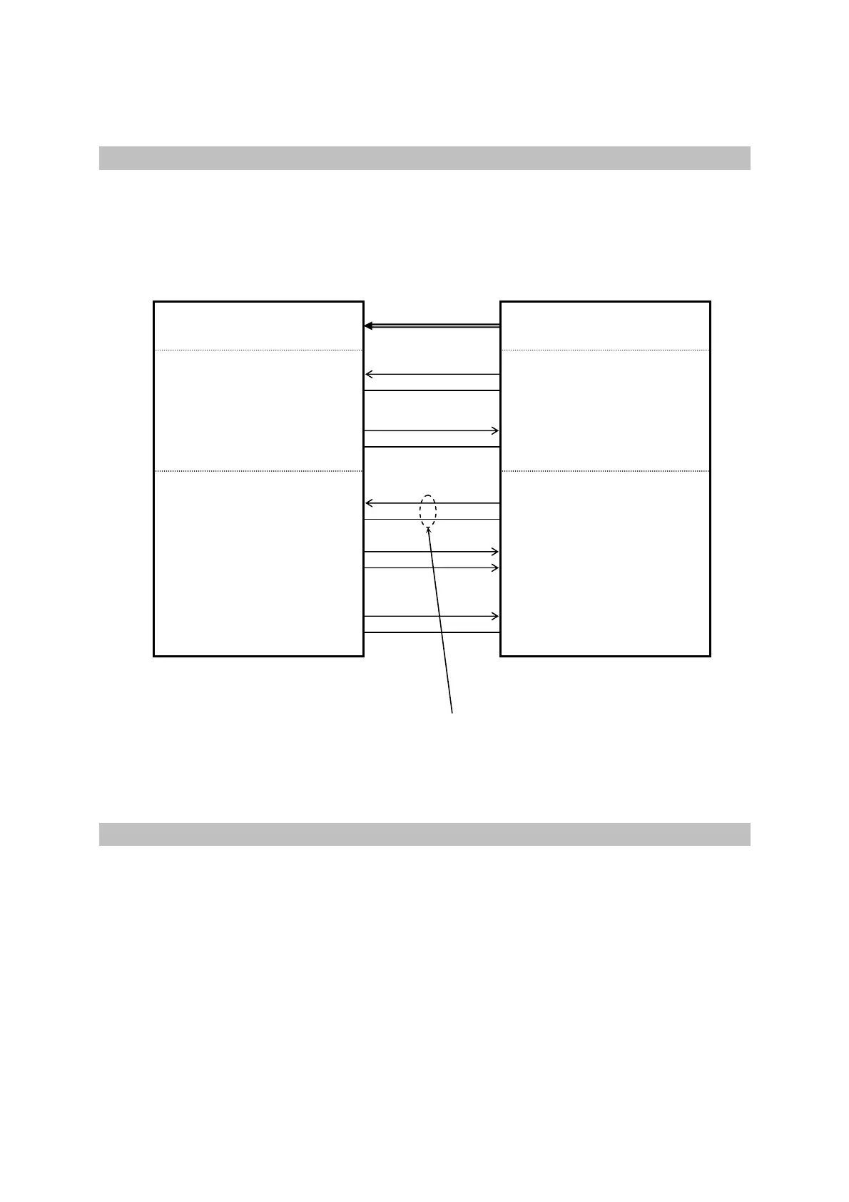
17.4 Connections
The following diagrams show how to use the safe disable function. They should be
considered as a generic reference example. Any specific machine/application design must be
analysed.
The risk of a short circuit between the safe disable wiring (-SR/+SR) and the 24V supply must
be minimized. Segregate the wiring in a dedicated raceway or use a shielded wire with
grounded shield.
17.5 Operation, sequence and timing
Follow the below stated sequence :
1.
Stop all the motors in a controlled way (zero speed).
2.
In case of vertical axes, activate the stationary brake against falling.
3.
Disable the drives (b41.5=0 or b40.9=0) and verify that b41.12=0 for both axes.
4.
Activate the safe disable function by removing voltage at the input –SR/+SR
5.
Verify the hardware feedback SC-A/SC-B and the software feedback b90.6
The clean contact SC-A/SC-B must be found close and the parameter b90.6=0 on both
axes.
At this time, the category 3 safety standstill has been achieved without motor-side contactors.
drive control / supervisor
analog or
field bus
IN0
0VQ
SC-A
SC-B
+SR
-SR
OUT1
0VQ
I/O-GND
Enable
HW
b 41.5
OUT0
0VQ
drive OK
b 41.4
Safety disable
feedback safety
rela
b 90.6
I/O-GND
I/O-GND
I/O-GND
pnp output
pnp output
input
input
 Loading...
