Parker Hannifin S.p.A. Divisione S.B.C. user’s manual TWIN-N and SPD-N
36
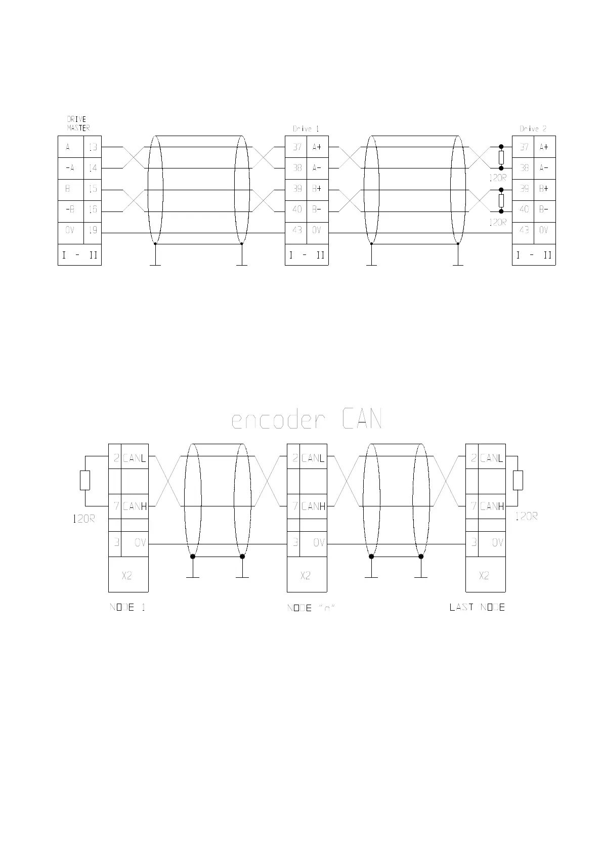
2.14.1 Connecting the drive to the digital-lock
In the example given above, the connection of two drives to the Digital-Lock with a master is shown,
but the diagram could be extended to several converters respecting the series connection. The line
charge resistors must be connected to the last converter. The master can be an encoder powered
externally or an encoder simulator of another converter.
The signal of the master encoder must in any case be of differential type 5V RS-422.
You can connect up to 32 converters to the electrical shaft by using the same signal of the simulated
encoder (standard RS-422).
Alternative at the reference in frequency it’s possible to execute a connection in digital lock by the
digital CAN bus on X2 connector. Follow the outline:
See par. “Digital Lock + Positioner” about the programming.
 Loading...
