Parker Hannifin S.p.A. Divisione S.B.C. user’s manual TWIN-N and SPD-N
134
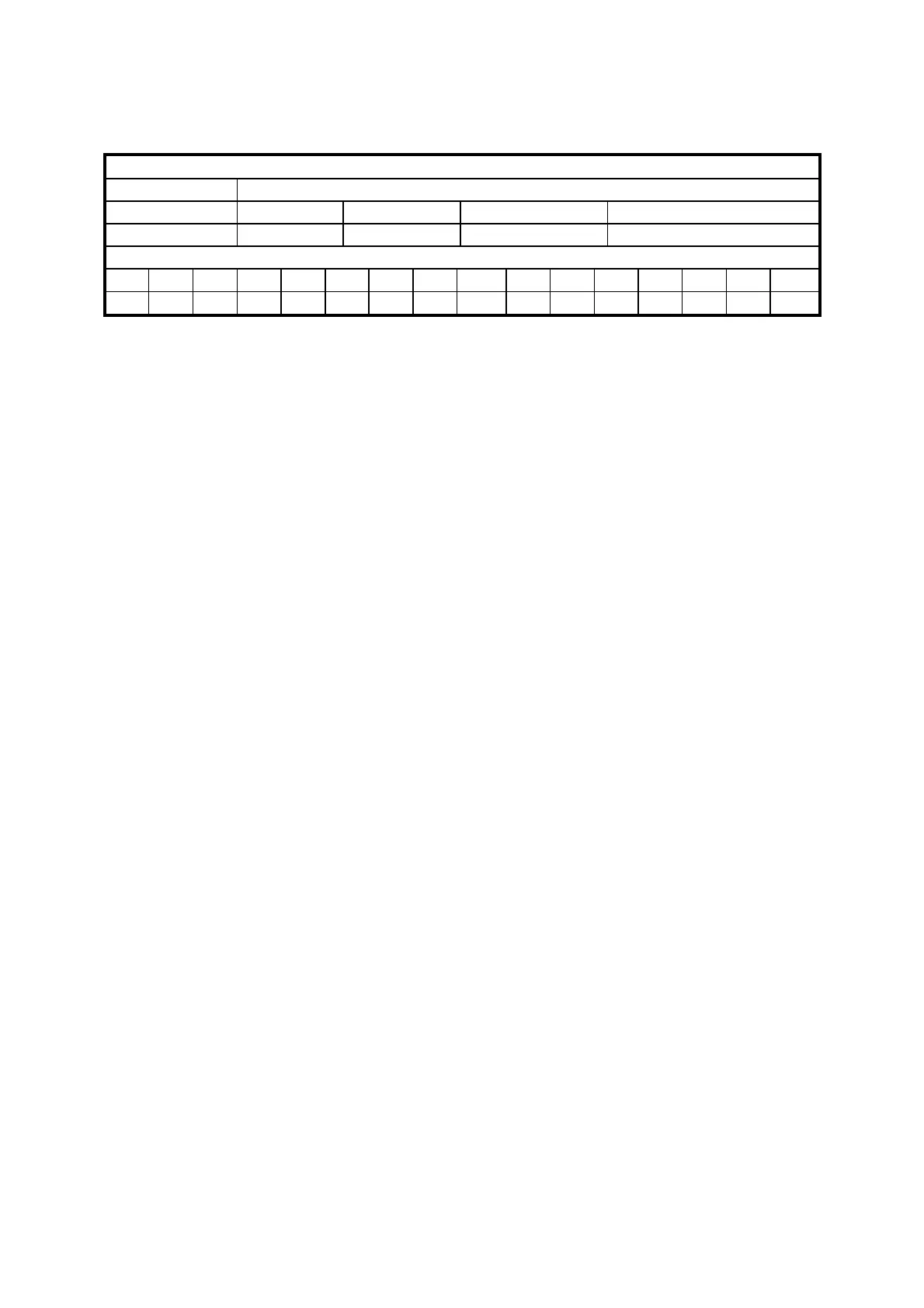
Emergency message from Drive to master
Emergency message
Data length
8 byte
Field Name
Error code Err. Reg Drive address Data
Contents
16 bit code 8 bit error 8 bit address 32 bit reply data
Identifier
ID2 ID1 ID0 - - - - - ID10 ID9 ID8 ID7 ID6 ID5 ID4 ID3
A2 A1 A0 X X X X X 0 0 0 1 A6 A5 A4 A3
A0:A6 Drive address (Pr49), valid values 1..127.
An alarm message and two pop-up messages are available for this object, and each of these
can be enabled or disables by setting the appropriate commands.
- Alarm message (enabled if b150.1=1)
- Target position reached (enabled if b150.5=1)
- Value motor captured (enabled if b150.7=1)
The alarm message, if enabled, is sent each time that the current alarm status (Pr[23])
changes, so that when a new alarm occurs (or when the alarms are reset) the value 0x01
is sent to the field Err.Reg, and the least significant byte of the Data field will contain
the drive’s alarm code.
The field Error Code will contain a specific code based on the different drive alarm:
- Er01 (over voltage) : 0x3210
- Er02 (under voltage) : 0x3220
- Er03 (over current) : 0x2340
- Er04 (encoder break) : 0x7310
- Er05 (over temperature motor) : 0xff07
- Er06 (over temperature drive): 0x4310
- Er07 (aux trip 1) : 0xff00
- Er08 (aux trip 2) : 0xff01
- Er10 (checksum PLC) : 0x6310
- Er11 (checksum Parameter): 0x6310
- Er14 (braking resistance alarm) : 0x7113
- Er15 (default Parameter) : 0x6320
- Er17 (calibration alarm) : 0x5210
- Er22 (over temperature ambient): 0x4110
- Er24 (over current braking): 0x7112
- Er25 (speed feedback error) : 0xff0e
- Er30 (hardware data memory) : 0x5530
When alarms are reset with b99.10, Error code will be 0x0000 .
Two additional pop-up message not related to alarms can be enabled using command bits, and
in this case the Err.Reg field will contain 0x00, while Error code will be 0xff05 for the target
position reached message and 0xff06 for the value drive captured message. The Data field, in
addition to the drive address, will, in the first case, contain the position reached by the motor
and, in the second case, the captured position of the motor on the positive front of the input
IN1.
 Loading...
