Parker Hannifin S.p.A. Divisione S.B.C. user’s manual TWIN-N and SPD-N
39
2.18 External braking resistance
The drive has an internal braking resistance. When a higher braking power is needed, it is possible to
connect an external braking resistance to the drive.
The external braking resistance value must be 40 Ohm and it is necessary to place a magneto-thermal
switch (or a fuse) between the external braking resistance and the drive.
The minimum cross section of the conductors depends on the drive size and it is equal to the
minimum cross section of the conductors between motor and drive (see paragraph “Power
connections”). It is necessary to minimize the connection cable length. In any case the cable length
must be less than 3 m.
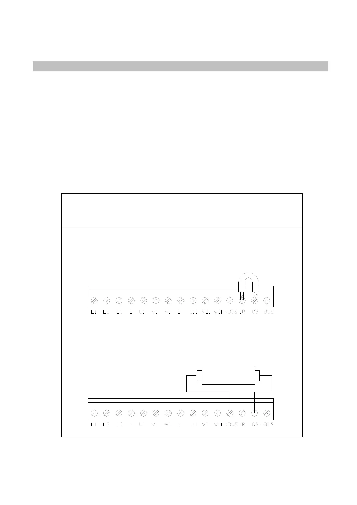
The connection of the external braking resistance is shown in the following pictures. The bridge
between IR and CB terminals (see pictures) enables the internal braking resistance; when the external
braking resistance is connected, the IR-CB bridge must be removed. Connect the external resistance
to the pins: +BUS and CB.
Resistenza Esterna
MORSETTIERA DI POTENZA
Resistenza Interna
R
RFE1
Internal resistance
External resistance
TERMINAL POWER
 Loading...
