Parker Hannifin S.p.A. Divisione S.B.C. user’s manual TWIN-N and SPD-N
170
Figure 17, Figure 18 and Figure 19 show the difference between the "set of set-points" mode
and the "single set-point" mode. The initial status of the bit ‘
change set immediately’ in the
controlword determines which mode is used. To keep simple these examples, only trapezoidal
moves are used.
If the bit ‘
change set immediately’ is "0" (continuously drawn line in Figure 17) a single set-
point is expected by the drive (1). After data is applied to the drive, a host signals that the data
is valid by changing the bit ‘
new set-point’ to "1" in the controlword (2). The drive responds
with ‘
set-point acknowledge’ set to "1" in the statusword (3) after it recognized and buffered
the new valid data. Now the host may release ‘
new set-point’ (4) and afterwards the drive
signals with ‘
set-point acknowledge’ equal "0" its ability to accept new data again (5). In
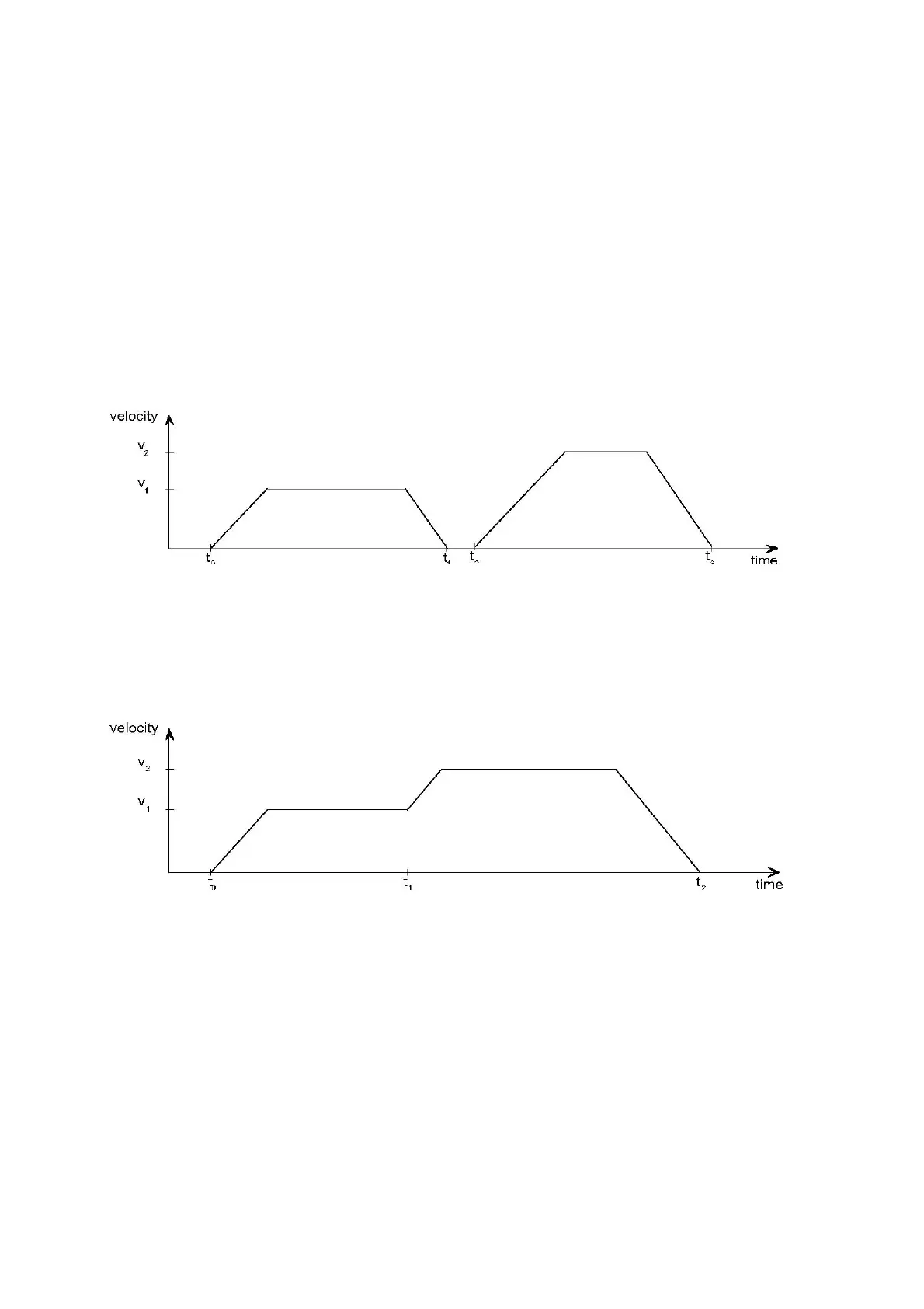
Figure 18 this mechanism results in a velocity of zero after ramping down in order to reach a
target position x1.at t1. After signaling to the host, that the set-point is reached like described
above, the next
target position x2 is processed at t2 and reached at t3.
0 12 3
Figure 18: Single set-point
If the bit ‘change set immediately’ is "1" (dashed line in Figure 17) the new target position
will be active immediately. In Figure 19 the drive receives the first
target position at t0. At
the time point t1 the drive receives a second
target position. The drive readapts the actual
move to the new target position immediately.
Figure 19: Change set immediately
10.3.9.4 Functional description
Figure 33 shows the meaning of the sub-function position reached. Symmetrically around the
target position a window is defined for the accepted position range. If a drive is situated in the
accepted position range over the time
position window time the bit target reached (bit 10) in
the
statusword is to set.
 Loading...
