Parker Hannifin S.p.A. Divisione S.B.C. user’s manual TWIN-N and SPD-N
184
Safety related systems and plants have to be designed by people skilled and trained as
required.
The category 3 safety standstill function in compliance with EN954-1 and EN13849-1
standards, is only guaranteed if all the feedback signals available from the drive (both
hardware SC-A/SC-B and software b90.6) are included in the machine / application safety
system, accordingly to the following instructions.
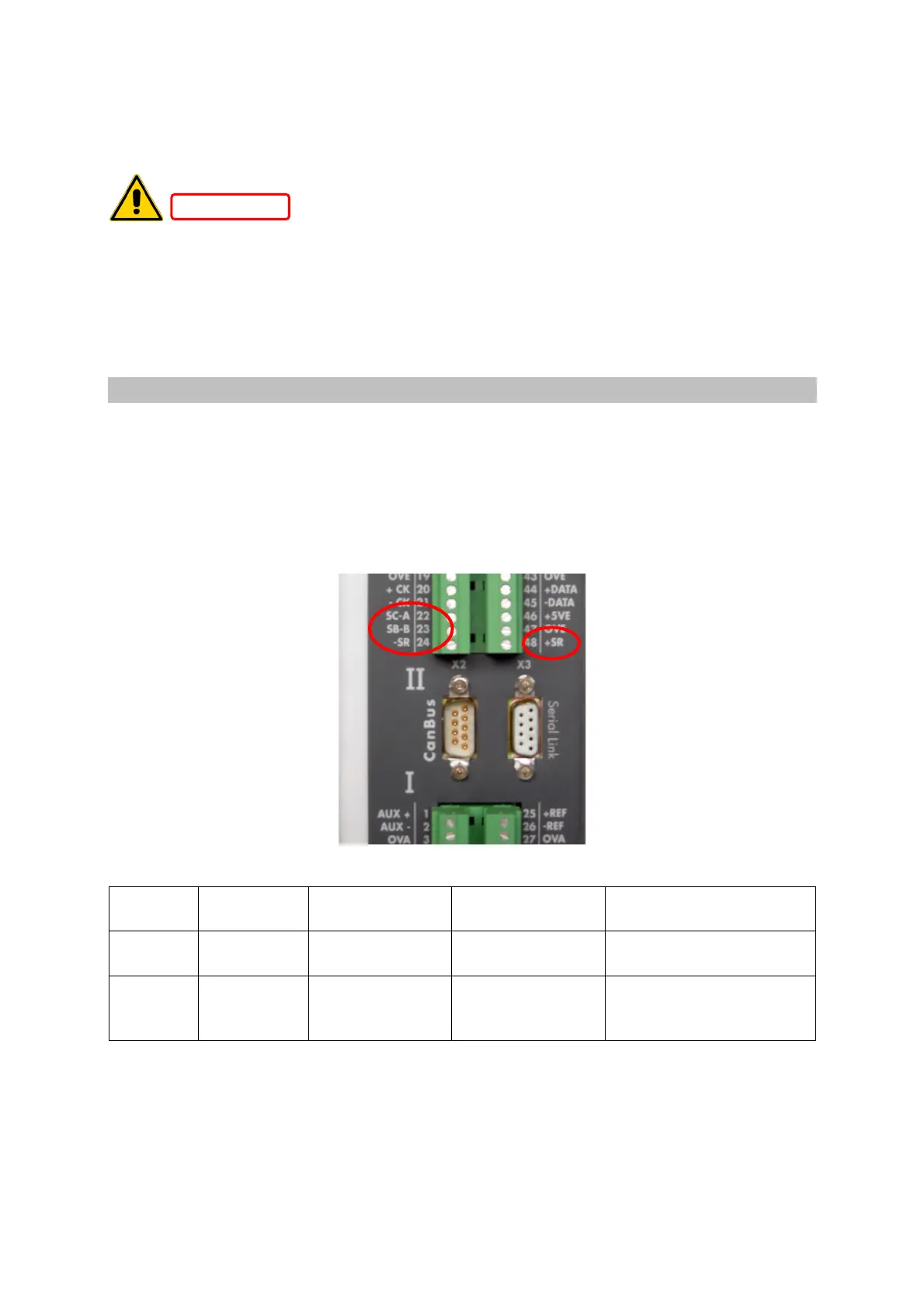
17.2 Signals description
On front side terminal box labelled with II following signals are connected:
•
safety relay activation command on terminals 24 and 48 (labelled SR+ and SR-)
•
safety relay feedback switch contacts on terminals 22 and 23 (labelled SC-A and SC-
B)
Terminal
box II pin
Signal Description Current
consuption
DC Voltage level
24-48 -SR / +SR Safe disable
command
33mA ± 10%
(@ 24Vdc)
24Vdc ± 10% (relay on)
< 1V (relay off)
22-23 SC-A / SC-B Feedback
NC potential free
switch
max 1A
24Vdc ± 10%
–SR/+SR input is protected against wrong polarity connections.
When +24VDC voltage is applied to terminal +SR with respect to terminal SR-, switching
ON the safety relay, power supply to output power stage of the drive is present, so the motor
movements are not safely stopped. Under this condition the safety relay feedback switch,
W
W
A
A
N
N
I
I
N
N
G
G
 Loading...
