Parker Hannifin S.p.A. Divisione S.B.C. user’s manual TWIN-N and SPD-N
46
5.4.1 Feedback configuration
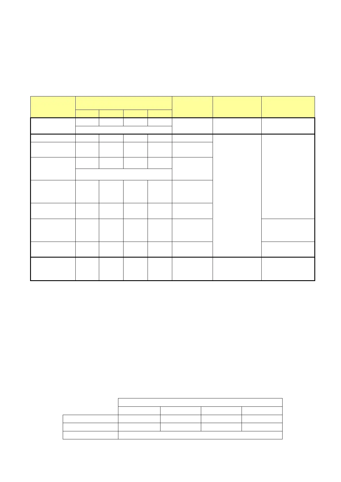
The following table reassumes all the possible configurations and indicates the relative formulation
of the parameters:
configuration Type motor
feedback
b42.9 b42.8 b42.7 b42.6
N. of pulses
revolution
Supply Drive code
0 0 0 0
Resolver
Default condition
- +ECC, -ECC
SPD-N
TWIN-N
Encoder
0 0 0 1
Pr196
Encoder less
wiring
0 0 1 0
Pr196
0 0 1 1
Encoder
sinusoidal +
Endat
Default condition
Pr196
(only read)
Encoder
sinusoidal +
Hiperface
0 1 1 1
Pr196
(only read)
Encoder
sinusoidal
0 1 0 0
Pr196
SPD-NE
TWIN-NE
SinCos One
sin wave per
pole pitch
1 0 0 0
Pr196
SPD-NF
TWIN-NF
Inc. encoder +
Hall sensor
1 0 1 0
Pr196
+ECC, -ECC
set the power
supply
(b231.6 e
b231.7)
SPD-NH
TWIN-NH
auxiliary
incremental
encoder
1 1 0 1
Pr196
+ 5VE, 0VE
(every available)
This selection configures the feedback of the speed control and of current and in the configuration of
default it is used also in the position control.
After to have saved the configuration the activation of the selected feedback happens to the
successive start-up of the drive.
5.4.2 Select supply feedback
The supply of feedback is between –ECC and +ECC pins.
With resolver feedback, the drive has a sinusoidal supply to 8kHz with short circuit and overload
protection, the value of voltage is 8V peak-peak.
With encoder feedback, the drive has a variable supply and the user must be set this value respecting
the electric characteristics of the device, following this table:
Supply voltage +ECC, -ECC
5 [Vdc] 5,5 [Vdc] 8,1 [Vdc] 8,6 [Vdc]
b231.6 0 1 0 1
b231.7 0 0 1 1
max current 250mA for each axis with short circuit protection
 Loading...
