Parker Hannifin S.p.A. Divisione S.B.C. user’s manual TWIN-N and SPD-N
171
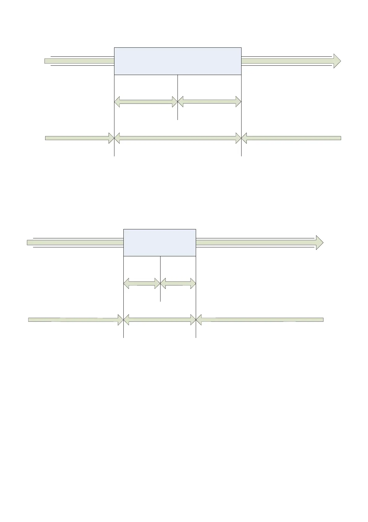
Position
Accepted position range
Position window
Position window
Position reached
Position not reached Position not reached
target position Figure 33: Position reached
Figure 34 shows the meaning of the sub-function
following error in the profile position mode.
Symmetrically around the reference position a window is defined for the accepted following
error tolerance. If a drive is situated out of the accepted position range for more than
following
error time out time the bit following error (bit 13) in the statusword is set.
Accepted following
Position
Error tollerance
Following
error
window
F
ollowing
error
window
No following error
F
o
llo
w
in
g
e
r
r
o
r
Following error
reference position Figure 34: Following error
The following error window is used to signal by mean of status word the servo error condition
on user defined BIT14 when Interpolated position mode is active and with standard bit 13 in
profile position mode. This feature isn’t valid for rel 206 yet.
If the user sets b272.3 a fault reaction sequence is entered and according to the fault reaction
option code(valid values 0,1,2) the motor is stopped and finally disabled sending an
emergency message with error code 0xff11 and user data loaded with pr[108:109].This
feature isn’t valid for rel 206 yet.
 Loading...
