92
between the TS and PC. (cf. “134.21 Coordinate axis definition”)
The
y are used for matching coordinate system between definition in the instrument and
definition in the external device when they are different. However, it is necessary to match the
definition of the “Coord. Axis” between settings in “Communication setup
” and settings in
“Coordinate axis definition
” when same coordinate systems are used.
z Factory default setting of SENDING
1.BAUD RATE: 9600
2.DATA LENGTH: 8
3.PARITY BITS: NIL
4.STOP BITS: 1
5.SIGNAL CONTROL: ON
6.XON/XOFF: ON
7.PROTOCOL: ON
8.RECORD DELIMETER: CR+LF
9.DISP.1 AXIS: BASIS DIRECT
10. DISP.2 AXIS: RIGHT ANGLE
11. DISP.3 AXIS: HEIGHT
12. ROTATION: CW
[3. SEND POLAR DATA]
Select the 3. SEND POLAR DATA and press [ENT] to view the following screen. Press [ENT] to open
the selection window.
Select each setting and press the [ENT].
Press [ACCEPT] to enter when all selections are finished.
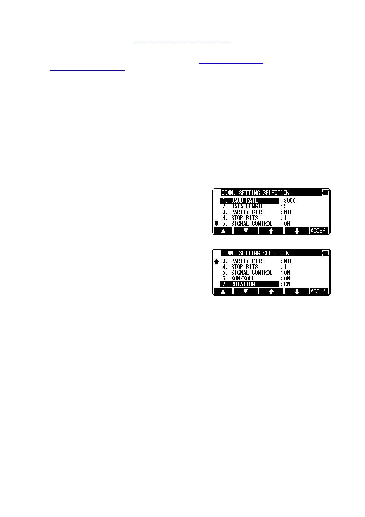
z Factory default setting of 3. SEND POLAR DATA
1.BAUD RATE: 9600
2.DATA LENGTH: 8
3.PARITY BITS: NIL
4.STOP BITS: 1
5.SIGNAL CONTROL: ON
6.XON/XOFF: ON
7.ROTATION : CW
13.4 About DataLink DL- 01 Software
DataLink DL01 Software allows you to send collected data by R-200 series to other devices,to
receive coordinates data, and to convert the resulting files into a number of common formats.
a) Recommendation for "PN"
It is recommended that "PN" (Point Name) data should consist of less or
equal to 4 (one-byte) numeric characters to convert files with DL-01.
Because, it may not be converted properly if alphabetic characters or
more than 5 (one-byte) numeric characters are used for the "PN".
b) Notes for the data transferring.
Please, be careful about following items for the data transfer with "DL-01".
b-1 Type of data, which can be transferred.
 Loading...