User’s Manual of IGS-10020HPT-U
28
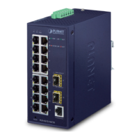
2.1.4 Switch Upper Panel
The Upper Panel of the Industrial Managed PoE+ Switch indicates a DC inlet power socket and consists of one terminal block
connector within 6 contacts. Please follow the steps below to insert the power wire.
1. Insert positive/negative DC power wires into Contacts 1 and 2 for Power 1, or Contacts 5 and 6 for Power 2.
IGS-10020HPT-U: 12V~54V DC
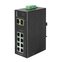
Figure 2-3: IGS-10020HPT-U Upper Panel
Tighten the wire-clamp screws for preventing the wires from loosening.
1 2 3 4 5 6
V1+ V1- V2+ V2-
Power 1 Power 2
Negative (-) Pin
IGS-10020HPT-U Pin 1 / 5 Pin 2 / 6
The wire gauge for the terminal block should be in the range from 12 to 24 AWG.

 Loading...