Setting Up the System
Topics:
▪ System Back Panel Ports
▪ LED Status Indicators for the G7500 System
▪ Complete System Setup
▪ Managing Peripheral Devices
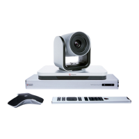
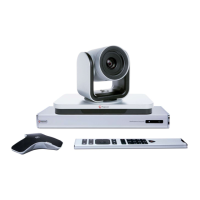
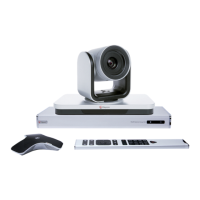
See the Polycom G7500 Setup Sheet for information on connecting your G7500 system and its peripheral
devices, including cameras, monitors, and microphones.
Also see the following documents for more setup information:
▪ Polycom G7500 Room Preparation Guide
▪ Polycom G7500 Mounting Kit
▪ Polycom Microphone IP Adapter Setup Sheet
▪ Polycom IP Ceiling Microphone Array Setup Sheet
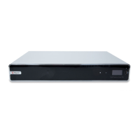
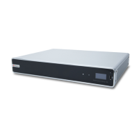
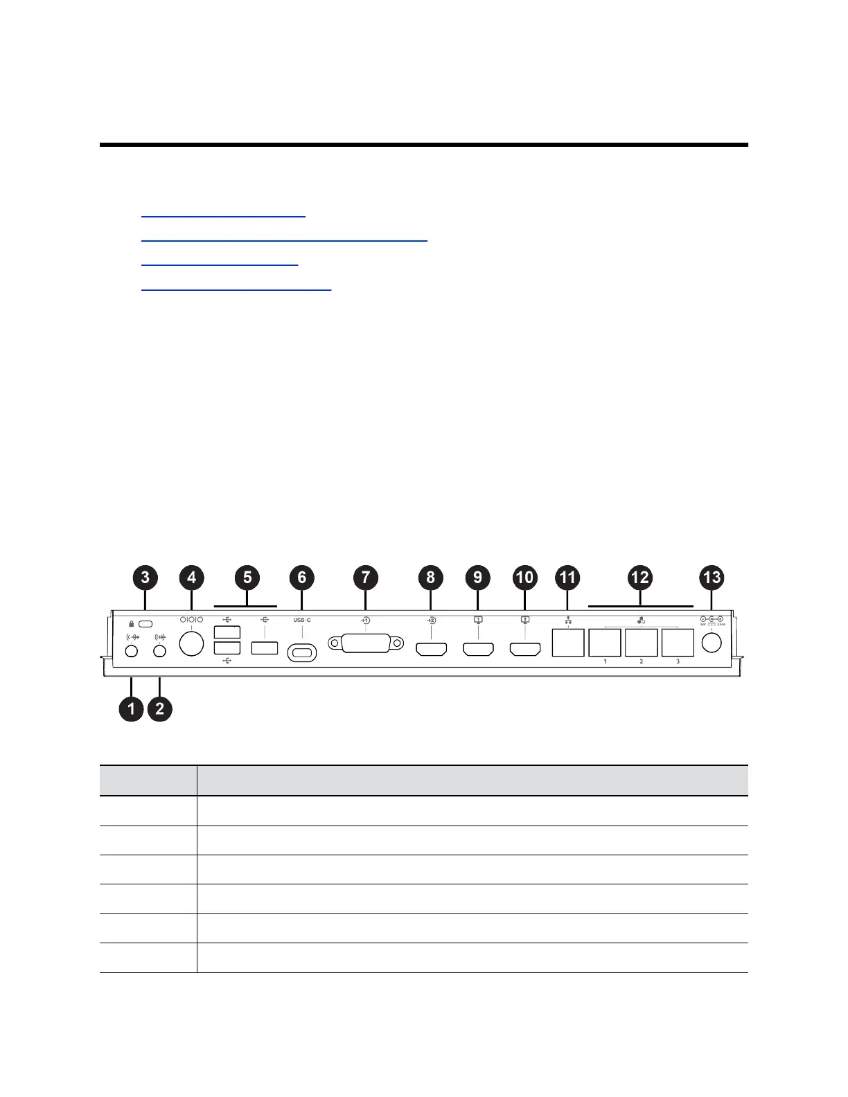
System Back Panel Ports
The following illustration and table explain the ports on the back panel of your G7500 system.
Figure 1: G7500 System Back Panel Ports
G7500 System Back Panel Port Descriptions
Ref. Number Port Description
1 3.5 mm audio line out
2 3.5 mm audio line in
3 Security lock
4 Mini-DIN/RS-232 serial port
5 USB 3.0 port (host)
6 USB-C port (dual-role port provides power only)
Polycom, Inc. 10