Polycom IP Ceiling Microphone Ports
The following illustration and table explain the ports on the ceiling microphone.
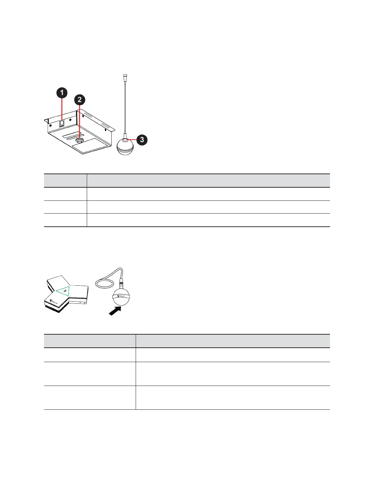
Figure 4: Polycom IP Ceiling Microphone Ports
Polycom IP Table Microphone Port Descriptions
Ref. Number Port Description
1 Link-local network (LLN) connection
2 Microphone cable connector
3 Microphone cable connector
LED Status Indicators for IP Microphones
Use the LED on the IP table and ceiling microphones to get information on the state of each device.
Figure 5: Polycom IP Table Microphone and Polycom IP Ceiling Microphone LED Locations
IP Microphone LED Status Indicators
Indicator Status
Solid then blinking white Powering on
Solid red Muted microphone
To avoid distraction, the ceiling microphone doesn’t display red when muted.
Solid green In a call
To avoid distraction, the ceiling microphone doesn’t display green in a call.
Setting Up the System
Polycom, Inc. 15