Personnel:
n
Skilled electrician
1. Install a power supply with adjustable output voltage to
supply the RMS supply input.
This is a requirement for voltage drop compensation.
2. Calculate the actual voltage drop between RMS power
supply and RMS.
3. Adjust the external RMS power supply to feed a slight
overvoltage of 5.1 V to 5.5 V depending on the measured
drop.
A measurement system contains integrated elec-
tronic components. Relating to the current con-
sumption Power Automation only indicates mean
values. Current peaks of a multiple of the mean
value may occur for several microseconds during
operation.
– Select a conductor cross-section which guar-
antees a maximum voltage drop of 0.2 V.
– Set the power supply to the upper limit of the
RMS supply voltage.
These steps guarantee that the RMS' supply
voltage does not drop below the required min-
imum.
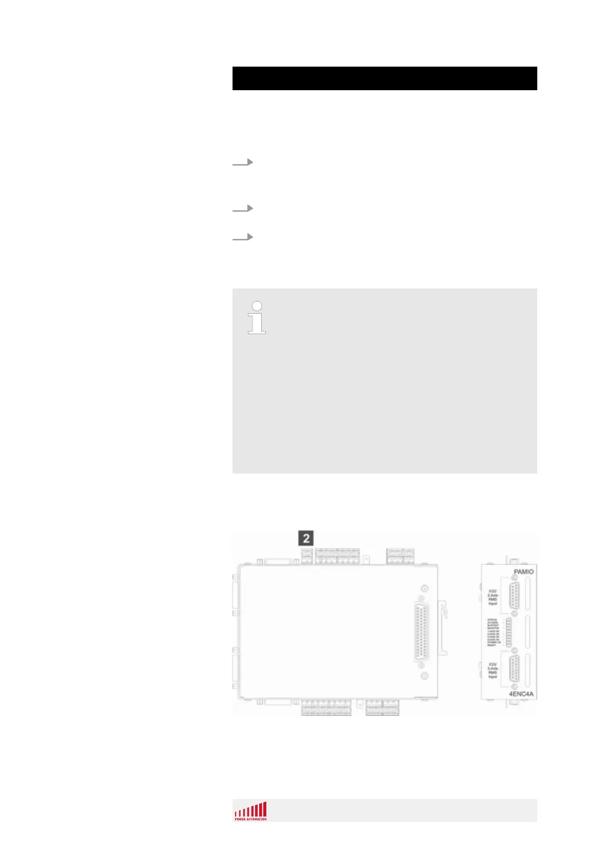
4.5.4 RMS Power Supply
Fig. 45: PAMIO 4ENC4A RMS power supply
2 Power supply input for RMS encoders (X35)
Compensation
Overview
PA 8000 PAMIO
PAMIO Components
12.01.2017 | 72
 Loading...