TARGAS-1 Operation Manual V. 1.02 113 support@ppsystems.com
• The external PAR sensor on the PLC5 Leaf Cuvette is calibrated. For protective measures you
can also compare the PAR sensor readings against a reliable quantum sensor.
• The PLC5 is attached to the TARGAS-1 and the light unit is connected electrically to the PLC5
Leaf Cuvette
• The Device Mode selection is PLC5
• The System has been on for at least 10 minutes.
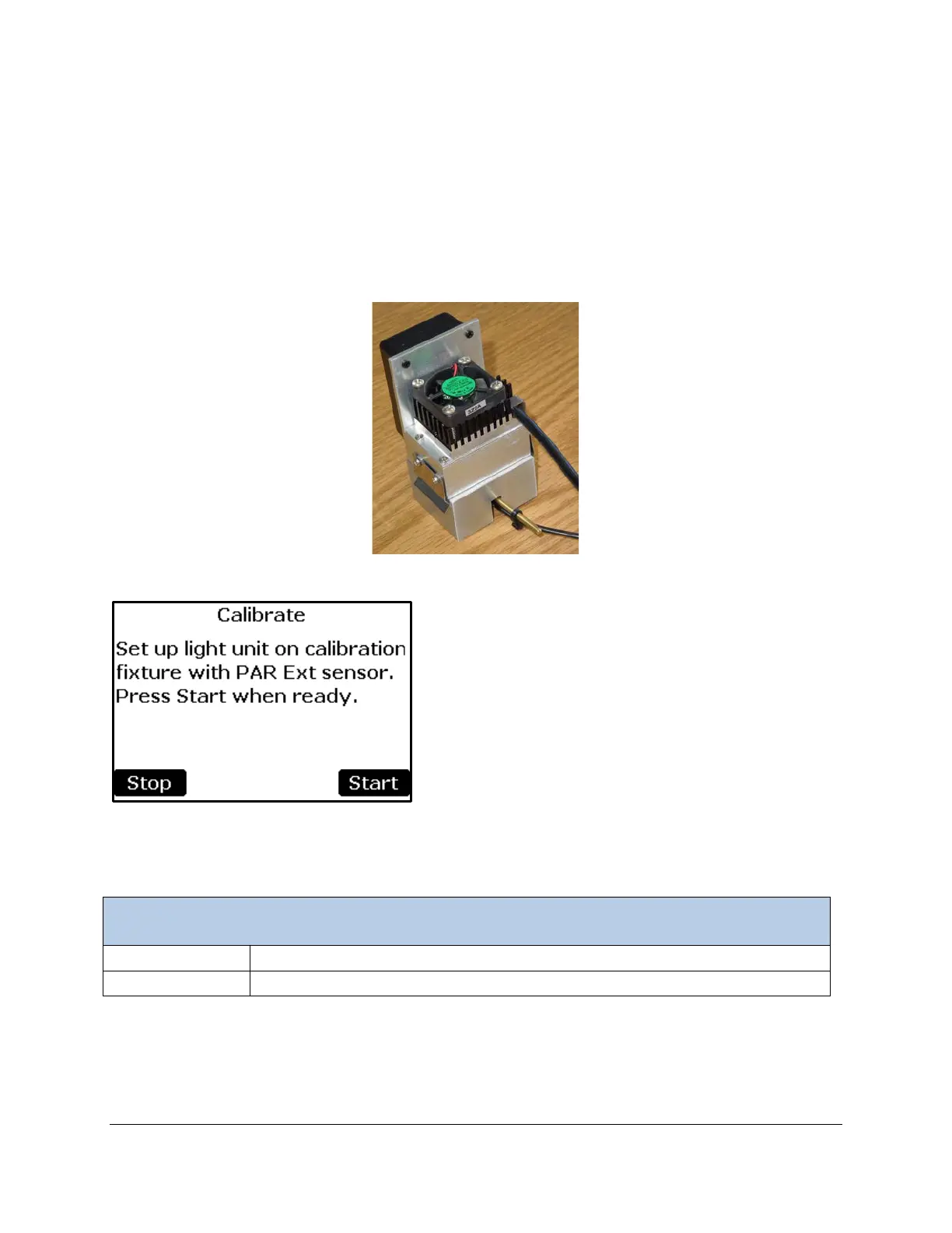
• The Light Unit is mounted to the light sensor calibration fixture (Part No. 20665-1) and placed flat
on the table and the external PAR Sensor is situated inside the calibration fixture as shown below
(after removal from the PAR Sensor holder on the side of the cuvette as shown below):
Important Note. The light unit calibration fixture (Part No. 20665-1) supplied with the system must be
used to accurately carry out the light unit calibration. If you do not have this you must contact PP
Systems to order a replacement.
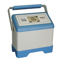
Returns to the Calibration Menu.
Start the Calibration process and proceeds to next screen