Page 14
Cable Entry
There are 6 cable gland knockouts on the base of the Ultra 5 (5 x M20,
1 x M16) and 4 on the rear (4 x 18mm dia (PG11)). Select which ones you
wish to take out, and remove them by using a circular cutter, such as a tank
cutter. Take care not to damage the circuit board inside whilst undertaking
this. Do not use a hammer, as this may cause damage to the enclosure.
It is recommended that you use suitable cable glands to ensure that the
ingress rating is maintained.
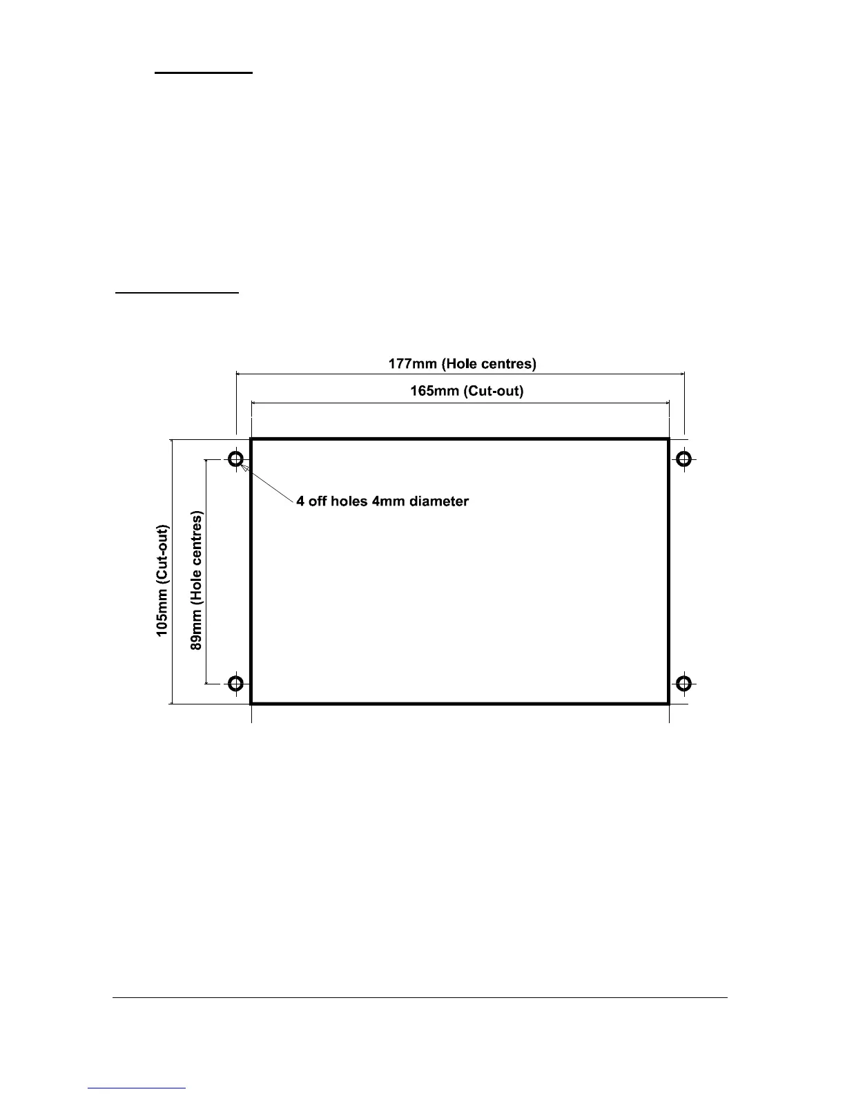
Fascia Mount
The Fascia mount Ultra 5 should be installed by cutting a hole in the panel
as detailed below.

 Loading...

