Page 84
Example 4 Differential Control
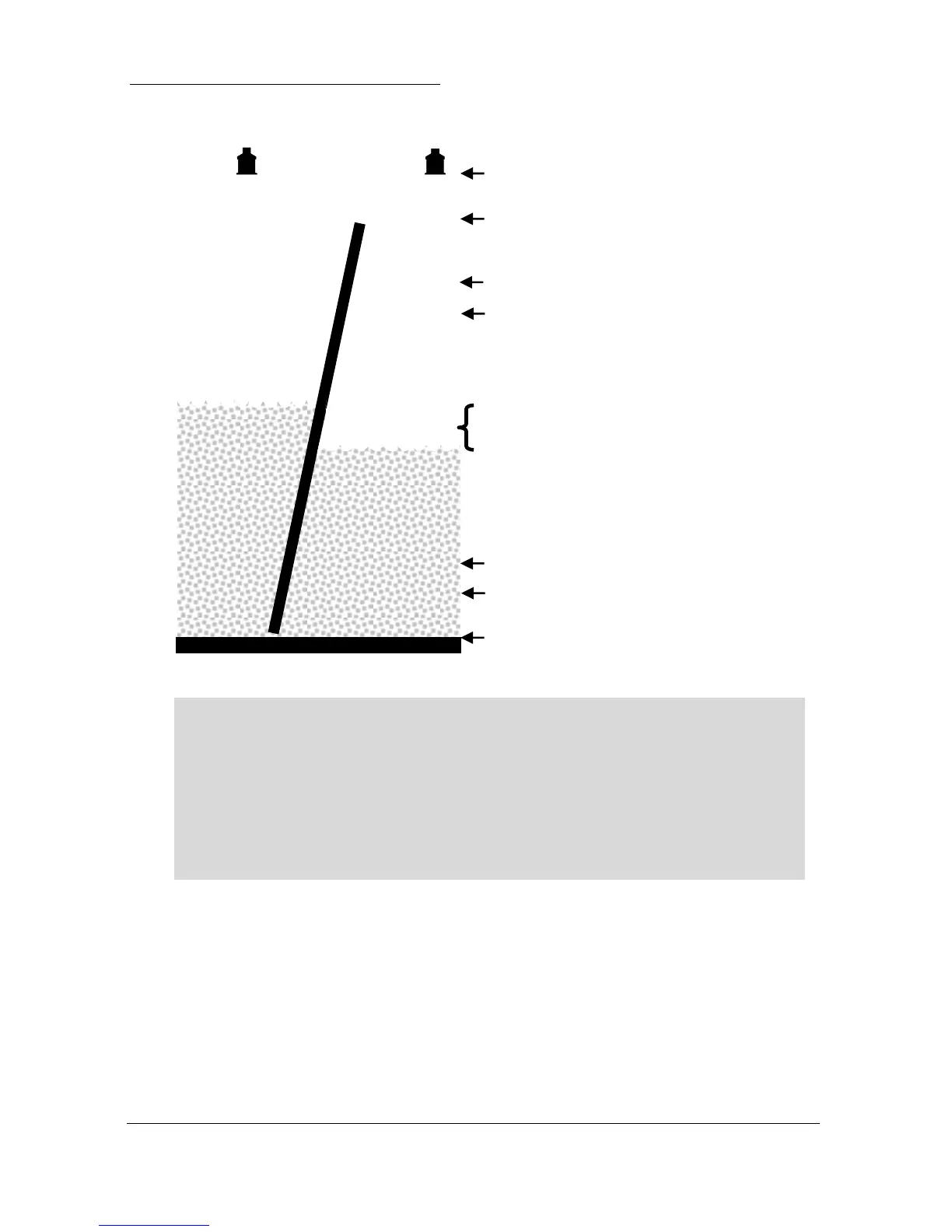
empty distance (P105), 3.5m
85% , Pt 1, high alarm on (P213), 2.38m
80% , Pt 1, high alarm off (P214), 2.24m
15% , Pt 2, low alarm off (P254), 0.42m
10% , Pt 2, low alarm on (P253), 0.28m
5%, Diff control, on, (223) 0.14m
1%, Diff. control, off, (P224) 0.03m
Note
When using the Advanced 5 to measure differential, the transducers should
be installed at the same height, to ensure that no differential is present when
the level is zero on both sides. If this is not possible then a measurement
offset (P851) or Display Offset (P802) must be applied to ensure the correct
reading is obtained.
In this example the Advanced 5 is being used to control a rake on a screen,
which is filtering out solids in the inlet flow to a wastewater treatment plant.
A high alarm has been assigned to Pt 1 (Transducer 1), on the upstream
side and a low alarm, to Pt 2 (Transducer 2) on the downstream side. The
Diff. Control, to operate the rake is on relay 1, high alarm, on Transducer 1
(upstream), is on relay 2 and, low alarm, on Transducer 2 (downstream) is
on relay 3.

 Loading...

