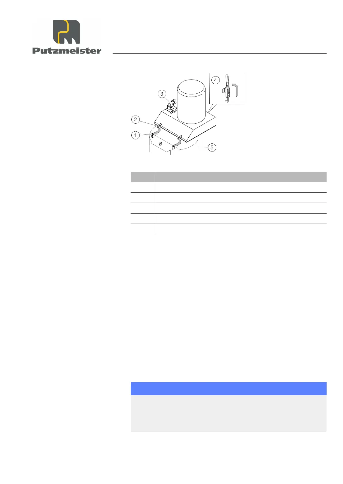
Figure 24: Injection hood
Item Designation
1 Clamping bolt
2 Locking pin
3 Sensor
4 Locking tensioner
5 Reservoir
2. Insert the injection hood with the locking pin on the reservoir and
secure it using the clamping bolts.
3. Attach the injection hood to the reservoir using the locking ten‐
sioner.
4. Connect the sensor to the conveying system using the control ca‐
ble.
4.8 Water connection
The following section describes how to connect the machine to the
water supply. The water supply network may only be connected as
per DIN 1988 - 4 and DIN EN 1717, i.e. by means of installation type
1 backflow preventers or an independent outlet (intermediate tank
with a pressure booster pump).
NOTICE
Machine damage caused by pipes freezing
▶
If there is a risk of freezing, the lines must be laid out so as to
exclude the possibility of the water freezing.
Transport, setting up and connection
4 — 17