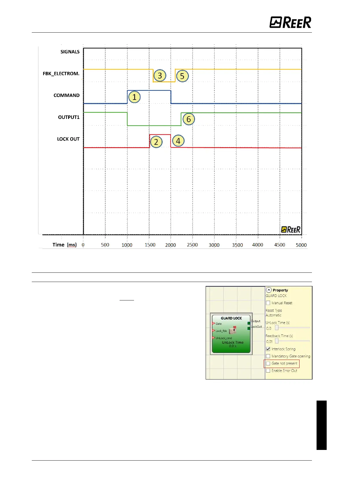
Figure 114 - Traces relative to “Guard Lock” block operation in the no gate mode.
Operation in the “with Gate” mode
In this case, the user must NOT select the “Gate not
present” parameter.
The Gate input must always be connected to an
“E-GATE” input element (see the E-GATE (safety gate
device) section on page 142) that verifies the status of
the door/gate.
The Lock_Fbk input must always be connected to a
“LOCK FEEDBACK” input element (see the LOCK
FEEDBACK section on page 144) that verifies the status
of the guard lock electromagnet.
The UnLock_cmd input can be connected freely in the
diagram and determines the request to unlock the guard lock (when set to LL1).
The Output signal is LL1 (TRUE) if the safety guard is closed and locked. When an unlock
command is applied to the UnLock_cmd input, the Output signal is set to LL0 and the
guard lock is unlocked via the LockOut signal. The Output signal can also be set to LL0
(FALSE) when error conditions are present (e.g. open door with guard lock locked,
Feedback Time exceeding the maximum allowed, etc.).

 Loading...


