When the Unlock_cmd signal is detected, the LockOut signal unlocks the guard lock after
the UnLock Time, a parameter that can be defined by the user.
The time after which the electromagnet is activated depends entirely on the
technical/physical characteristics of the specific device and may therefore vary according
to the type of guard lock used. Thus, since the LockOut signal controls the activation of
this device, the status of the Lock_Fbk feedback signal will change at different times,
depending on the type of guard lock. This variability can be avoided by changing the value
of the Feedback Time parameter, which is the maximum delay accepted by the
“Guard_Lock” operator before the Lock_Fbk signal switches status following a request to
activate the electromagnet. Clearly, the following condition must be met:
Feedback Time ≥ Electromagnet activation time
This will now be explained using a practical example.
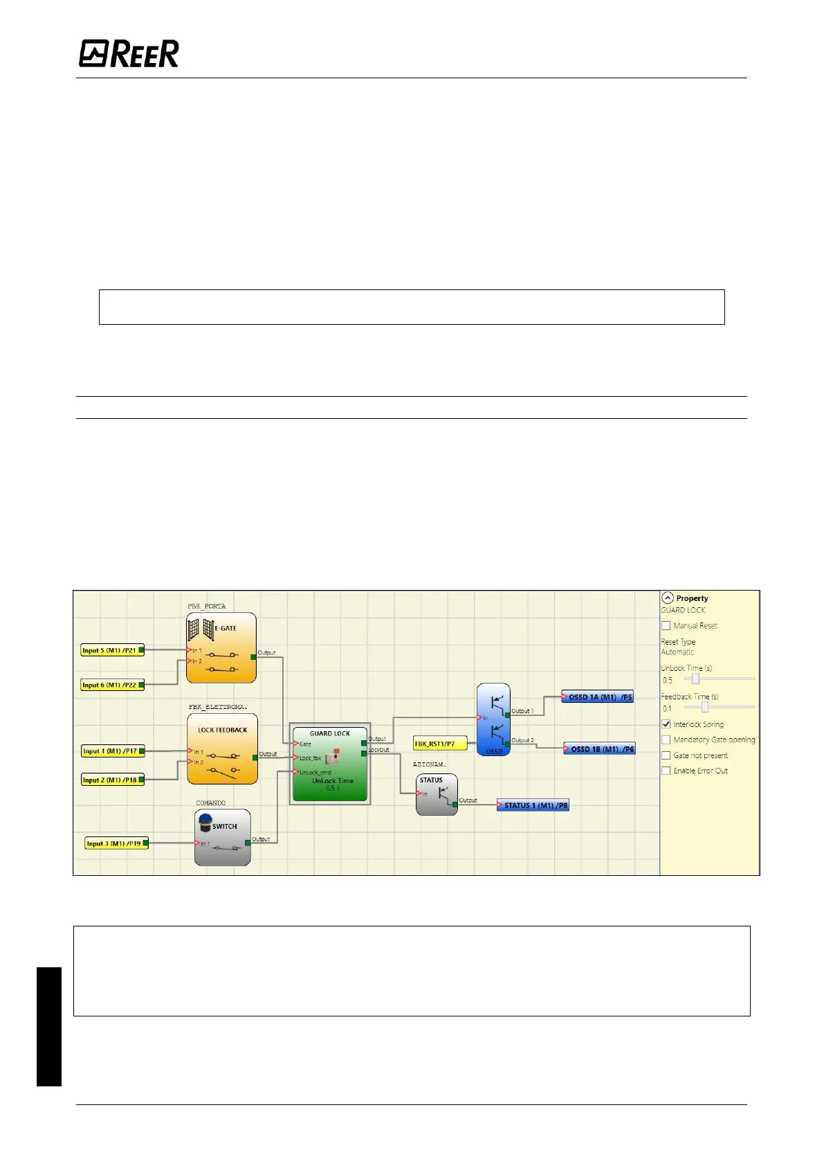
Example of operation in the “with Gate” mode
In this example the user unlocks the guard lock with the “SWITCH” block. The “LockOut”
signal controls an “STATUS” SIL 1/PL c output that controls the guard lock electromagnet,
the status of which is detected by the “Lock_fbk” input via the “LOCK FEEDBACK” input
block. “Output1” indicates the status of the operations.
The status of the safety gate is monitored by the "Gate" input via the "E_GATE" input.
The guard lock used in the example continues to be locked when the electromagnet is not
energised. Therefore the "Interlock spring" option must be selected.
Figure 115 – Example of operation in the with Gate mode
➔
The Guard Lock operator parameters are shown on the right. On the left there is an example of an
application diagram. The electromagnet feedback consists of two contacts, one normally closed
and one normally open. When the electromagnet is energised the two contacts switch status. The
gate feedback consists of two normally closed contacts.

 Loading...


