88
2004 – 2014 Reliable Controls
®
Corporation. All rights reserved.
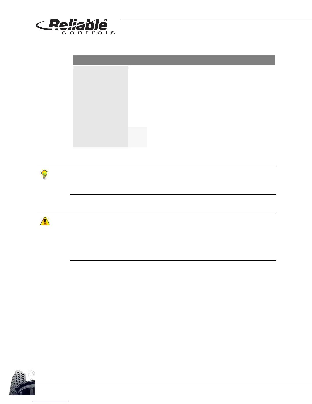
TABLE 19: SS-L ONBOARD FLOW TOOL CONFIGURATION PARAMETERS
Parameter Function
FLO Displays the current calculated measured flow
FL-CAL Used to enter the actual measured flow
FL-OVR Used to override the current airflow setpoint
FI-MIN Display/modify the minimum airflow setpoint
F-MAXO Display/modify the maximum occupied airflow setpoint
F-MAXU Display/modify the maximum unoccupied airflow setpoint
CW-CLS
Off Actuator rotation counter-clockwise to close damper
On Actuator rotation clockwise to close damper
Before using the Flow Tool to perform airflow calibration of a MACH-Air
™
or MACH-ProAir
™
controller, set the minimum (VAVx-FLO-MIN) and maximum airflow setpoints (VAVx-FLO-
MAX-OCC, the VAV box inlet duct diameter (VAVx-DIAM-IN) and the damper actuator
rotation direction to close (VAVx-CW-CLS).
The following MACH-Air
™
/MACH-ProAir
™
airflow calibration procedure as outlined in
Reliable Controls
®
Application Notice 0009 assumes a functional and configured controller.
The calibration procedure requires stable duct static pressure. The central air handling
system should be controlling to the design duct static pressure setpoint. Significant
changes to the VAV box inlet static pressure during the calibration procedure will result in an
inaccurate calibration. For best practice, set all connected VAV boxes to 50% of the
maximum flow setpoint using the FLO-SP-OVR variable.