89
Flow Tool
USER GUIDE
ONBOARD CONFIGURATION TOOLS (SS-L)
SMART-SENSOR
™
2004 – 2014 Reliable Controls
®
Corporation. All rights reserved.
TO USE THE SS-L FLOW TOOL
1 Access the Flow Tool using the appropriate key code combination outlined in
Ta bl e 17.
2
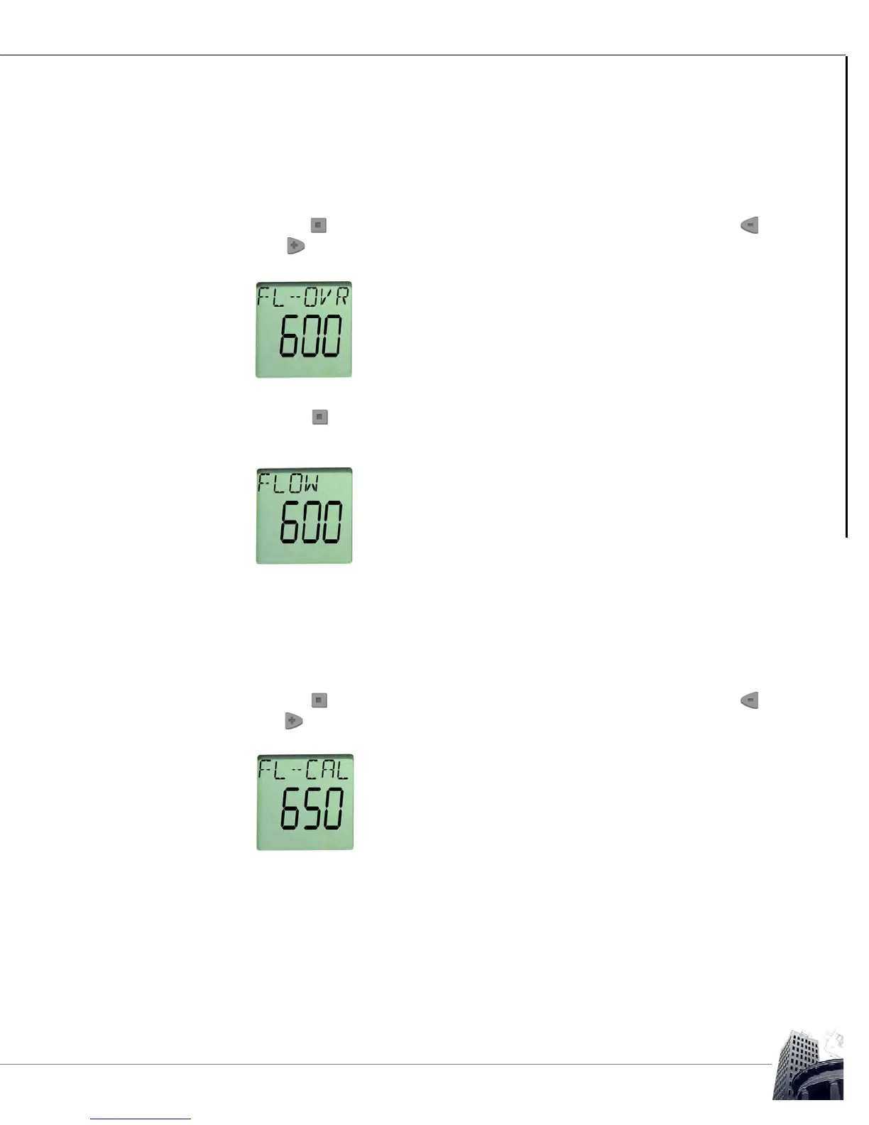
Use the button to step to the FL-OVR point on the SS-L. Then use the
and buttons to override the current airflow setpoint to the maximum
occupied airflow setpoint for the connected VAV box.
FIGURE 77: SS-L FL-OVR POINT
3
Use the button to step to the FLOW point on the SS-L and wait until the
displayed calculated flow stabilizes (depending upon system conditions and
flow sensor calibration, the displayed flow may not reach the FL-OVR setpoint).
FIGURE 78: SS-L FLOW POINT
4 Determine the actual VAV box total airflow by measuring the airflow through
each connected distribution outlet using an accurate balancing hood.
For this example, the initial calculated flow is 600 CFM but the actual measured
total flow is 650 CFM.
5
Use the button to step to the FL-CAL point on the SS-L. Then use the
and buttons to increment the value to the actual total measured airflow
recorded in step 4.
FIGURE 79: SS-L FL-CAL POINT