The engine Section F
7 Recut the valve seats
to
ensure that the seats
are concentric
with
the
va
l
ve
stem bore.
8 Relap valves
to
cylinder head seats, after
this operation carefu
lly
check valve seats to
ensure that no grinding paste particles are
present.
9 Fit n
ew
valve springs and
new
cotters
if
necessary.
10
Replace cylinder head.
Operation
11
-
Pi
stons, connecting
rods and bearings
(w
ith cylinder
head and sump removed)
1 Remove oil pump
as
.sembly (see
Operat
io
n
4)
.
2 Release locking plates, unscr
ew
eight bolts
and
rem
ove the four big end b
ea
ring caps (see
Fi
gure
15)
.
3 Remove the bearing shells from the caps
and con rods.
4 Carefully push the pistons, complete
with
con rods from the cylinder liners.
5 Immerse piston and con rod assemblies in
hot
water
for
a
few
minutes then release
gudgeon pin retaining circlips.
6 Using a suitable drift remove the gudgeon
pi
ns
and disconnect the con rods from the
pistons.
7
Rem
ove the small end bush
es
from the con
rods, and press in n
ew
on
es.
8 Having pressed in
new
small end bushes
check that they
will
accept
new
gudeon pins
for
it
may be necessary to ream
out
the bushes
with
an expanding reamer until a
tight
push
fit
is obtained.
Note
:
It
is important during this operation that
the bush is reamed squarely to the con rod
to
.
ensu
re
correct alignment.
9 Assemble
new
pisto
ns
Jo
the connecting
rods, securing in position with the gudgeon pins
and circlips.
It
may
be
necessary to heat the
pistons in hot water to facilitate the operation.
Ensure the
'f
ront' mark on the piston crowns
are
facing forward.
10
Before fitting t
he
piston rings, position in
appropriate liners for gapping, which should be
0·
17-0
·30mm (0·007- 0·012in).
11
11 Fit the piston rings, fitting the scraper ring
first, followed by the lower and then the upper
compression rings. The
'to
p' mark on the
compression rings must face uppermost.
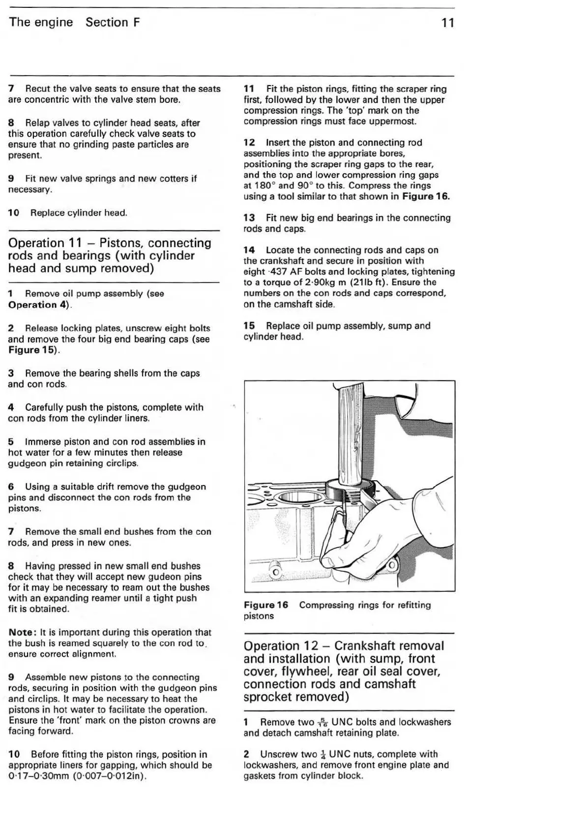
12
Insert the piston and connecting rod
assemblies into the appropriate bores,
positioning the scraper ring gaps
to
the rear,
and the
top
and l
owe
r compression ring gaps
at
180
° and
90
°
to
this. Compress the rings
using a
tool
similar
to
that
shown
in
Figure
16
.
13
Fi
t
new
big end bearings
in
the connecting
rods and caps.
14
Locate t
he
connecting rods and caps on
the crankshaft and secure in position
with
eight
·4
37 AF bolts and locking plates, tightening
to a torque
of
2·90kg m (21lb
ft)
.
Ensu
re the
numbers on the con rods and caps
co
rre
spond,
on the camshaft side.
15
Replace oil pump assembly, sump and
cylinder head.
Figure
16
Compressing rings for refitting
pistons
Operation
12
- Crankshaft removal
and
in
stallation
(with
sump, f
ront
cover,
flywh
ee
l, r
ea
r
oi
l
sea
l cover,
connection rods and camshaft
sprocket removed)
1 Remove
two
fir UNC bolts and lockwashers
and detach camshaft retaining plate.
2 Unscrew
two
i UNC nuts, complete
with
lockwashers, and remove front engine plate and
gaskets from cylinder block.