The engine Sec
ti
on F
3 Unscrew
four
-h
UNC
set screws and
remove rear engine plate from
cylinder block.
4 Remove four screws and detach the front
and rear bridge pieces from the
cylinder block.
5 Disconnect all three main bearing caps,
after removing six
i UNF nuts and washers,
two
each cap (see Fig
ur
e 15).
6 The crankshaft can
now
be
withdrawn
from the cylinder block.
7 Check crankshaft main bearing journals (see
engine specification for details).
8 Fit new main
bea
rings to crankshaft and
bearing caps.
9 Fit
new
thrust washers to the crankshaft
ensuring that the thrust
fa
ce
of
the first washer
makes
good
contact
with
the ground face
of
the
crankshaft.
1
0 Replace crankshaft to cylinder block, fit
main bearing caps
in
order, rear. centre, front,
and secure to block
with
six i UNF nu
ts
. Always
fit
new
main bearing cap nuts and tighten to a
torque
of
3·316kg m
(24
lb
ft).
11 Permitted end float
of
crankshaft is
0·
0254-0
·1524mm (0·
001-0
·006in).
12
12
Replace components in reverse order,
taking note
of
the
following
. When refitting front
and rear bridge pieces care should
be
taken to
ensure that their faces mate flush
with
the
cylinder block face.
Operation 13 - Camshaft removal
and installation
(with
timing chain
and sprocket removed)
1 Remove engine assembly (see
Operation
1 ).
2 Unscrew
two
-h
UNF nuts and
lift
off
rocker cover and sealing gasket.
3 Unscrew four
i UNF nuts and washers
from the rocker shaft support brackets and
remove the complete rocker assembly.
4 Withdraw the eight push rods keeping
them in their correct order.
5 Remove sump (see
Operatio
n 3).
6 Unscrew
two
-h nuts, complete
with
lockwashe
rs
, and remove oil pump assembly,
complete
with
filter, from cylinder block.
7 Knock
out
the pin
se
curing thrust
muff
to
distributor and oil pump drive shaft
which
can
then
be
removed upwards through the
distributor location.
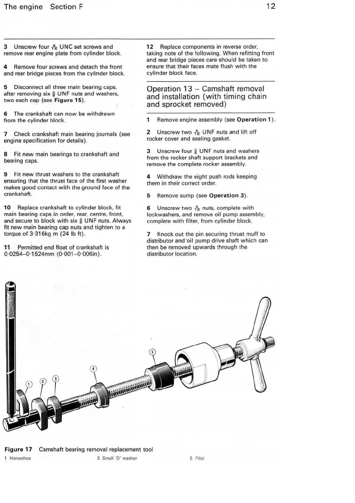
Fig
ur
e
17
Camshaft bearing removal replacement
too
l
1 Horseshoe 3 Small
'D'
washer 5 PilOt