DURADRIVE Drive Controllers DURADRIVE HDC01.1 Drive Controller 4-33
DOK-DURADR-HDC01.1****-PR02-EN-P
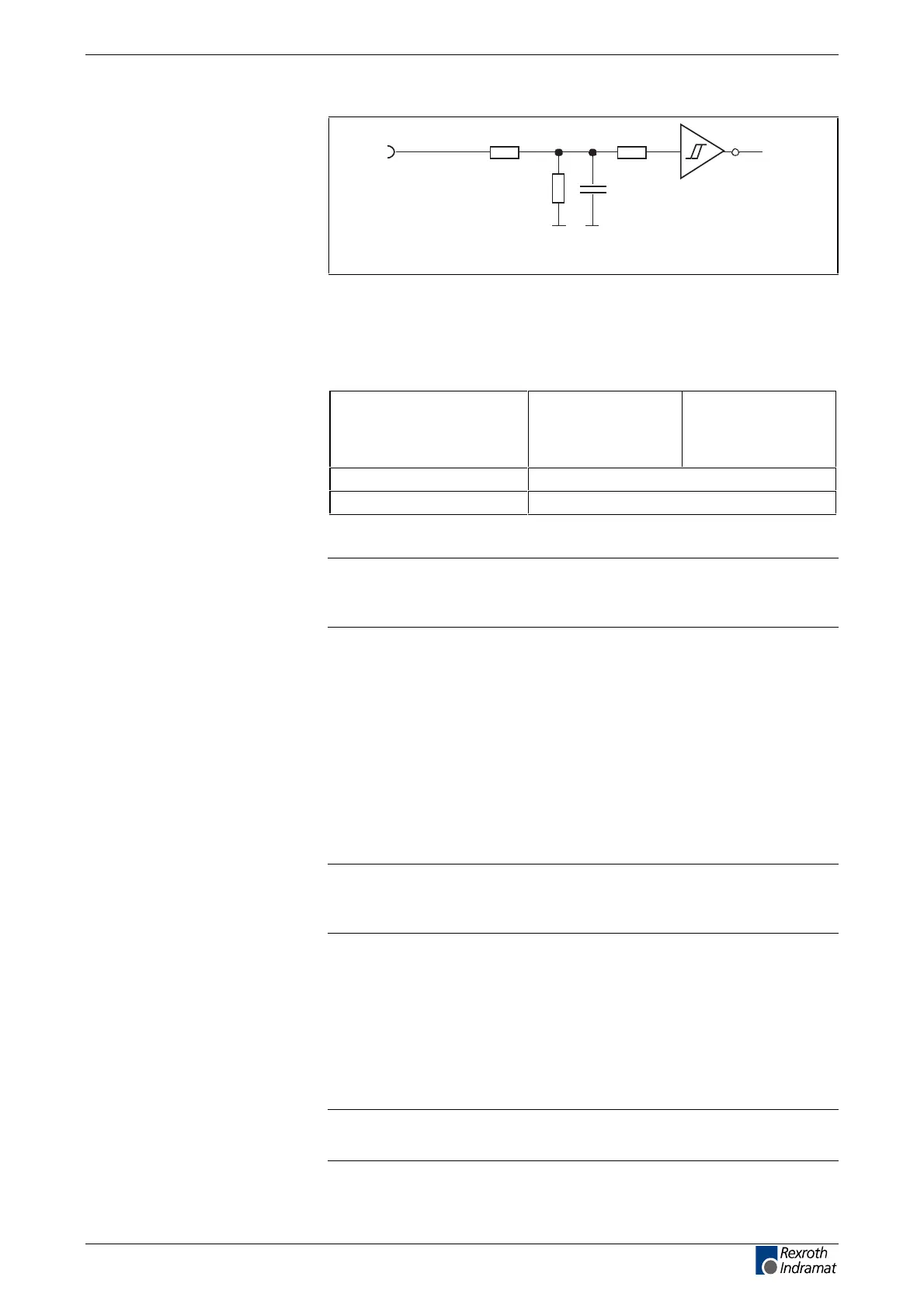
R1 R3
R2
C1
I
n
Ap5183f1.fh7
Schematics
R1: 10k
R2: 3k3
R3: 10k
C1: N/A.
Fig. 4-48: Input circuit
Input voltage:
High
Low
min.
16 V
-0,5 V
max.
30 V
3 V
Input resistance 13,3 kOhm ± 5%
Reaction time See firmware functional description
Fig. 4-49: Inputs
Note: If the inputs are controlled by a power supply other than the
DC24 volt supply of the HDC, then the reference lead of the
other power supply must be connected to X3.18 (OV).
The positive edge of the homing switch is always evaluated.
End switches can be N/C or N/O depending on how the drive is
parameterized. See firmware functional description.
Position and time measurements are read using two binary input signals.
Switching-signal dependent continuous block switching makes transition
to the next block possible with the use of an external switching signal.
Note: If the functions probe and following block mode are
simultaneously activated, then both functions evaluate the
inputs independently of each other.
At delivery, the E-stop function is deactivated depending on what has
been parameterized. See firmware functional description.
With a positive edge at the input "clear error", all errors (up to four) are
cleared. With the actuation of the S1 button (firmware module) only the
error in the display is cleared and any other errors present are then
shown.
Note: The errors entered in the back-up memory are not cleared with
the "clear error" input.
Input circuit
Digital inputs
Inputs
Digital inputs
Homing switch
Limit+, Limit-
Probes
Cams
E-Stop
Clear error
LSA Control S.L. www.lsa-control.com comercial@lsa-control.com (+34) 960 62 43 01