DURADRIVE Drive Controllers DURADRIVE HDC01.1 Drive Controller 4-37
DOK-DURADR-HDC01.1****-PR02-EN-P
The analog differential inputs 1 and 2 can be parameterized as needed
and can be used, for example, as an analog speed command value
inputs, override inputs or for analog torque reduction.
⇒ See also firmware function description: "Analog inputs".
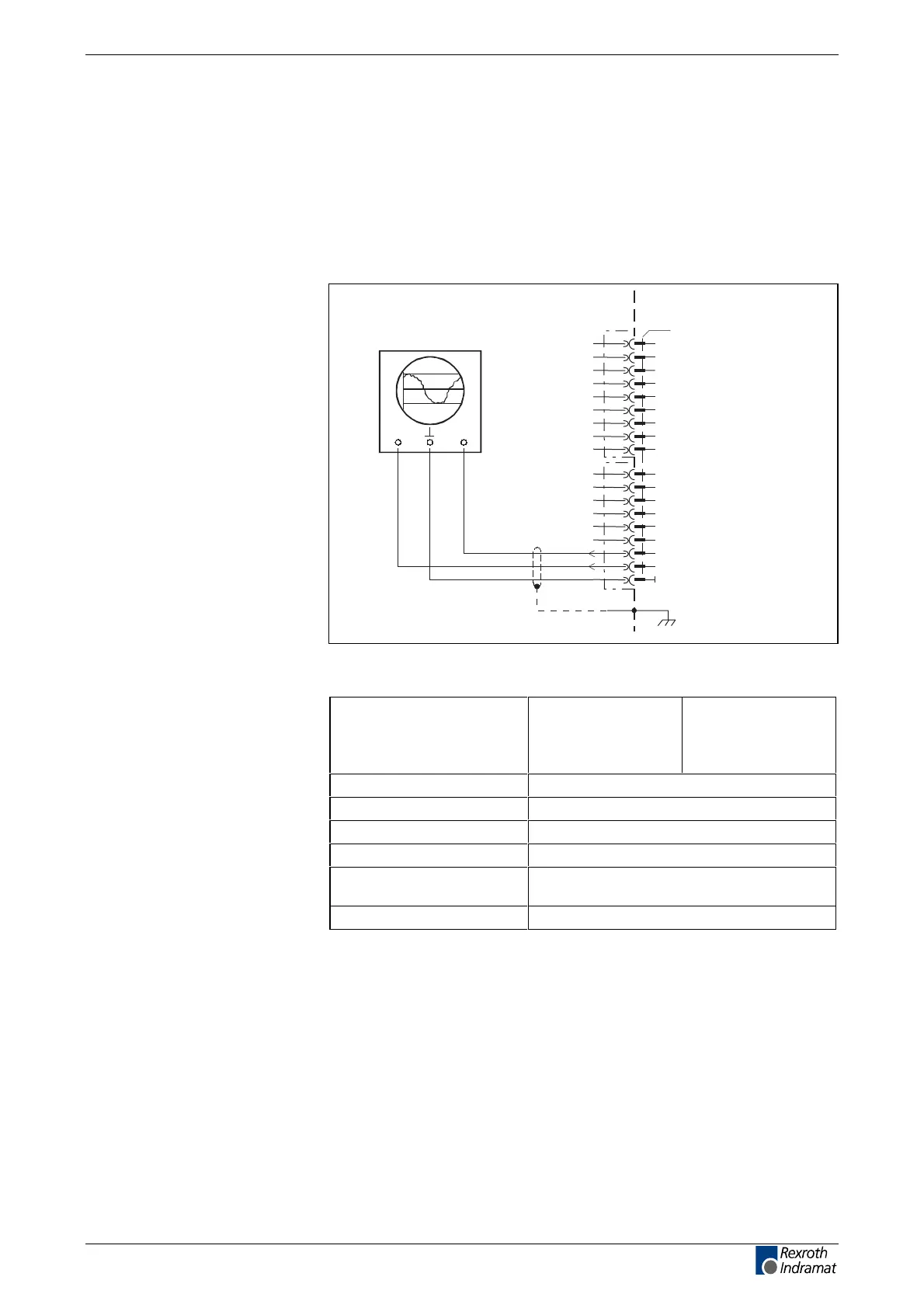
Analog outputs 1 and 2
AP5279F1.FH7
1
3
4
5
6
7
8
9
10
11
X3
12
13
14
15
16
17
18
2
for example: oscilloscope
CH1 CH2
0V
analog A2
analog A1
XS2
Fig. 4-57: Connection example of outputs A1 and A2
Output voltage
between A1 & 0 V:
between A2 & 0 V:
min
- 10 V
- 10 V
max.
+ 10 V
+ 10 V
output current max. 2 mA
output resistance 150R
DA converter 8 Bit
Resolution per bit 78 mV
short-circuit and overload
protection
not present
Probe See firmware functional description
Fig. 4-58: Outputs
Analog outputs 1 and 2 can be freely parameterized and used for
diagnostics or implementation of master/slave mode.
⇒ See also firmware functional description: "Analog outputs".
Analog inputs
Connection
Analog outputs
Outputs
Analog output
Analog outputs
LSA Control S.L. www.lsa-control.com comercial@lsa-control.com (+34) 960 62 43 01
 Loading...
