DURADRIVE Drive Controllers DURADRIVE HDC01.1 Drive Controller 4-59
DOK-DURADR-HDC01.1****-PR02-EN-P
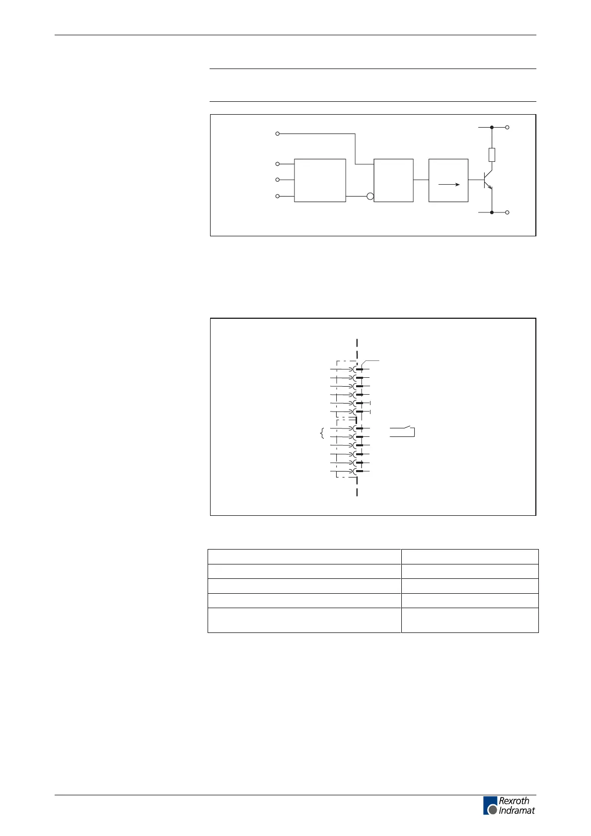
Note: If mains voltage applied at X5 then DC bus dynamic brake not
executed!
ZKS-
requirement
X11
L1
L2
L3
mains
voltage
detection
&
t
d
R
ZKS
L+
L-
Ap5193f1.fh7
Fig. 4-104: Block diagram interlock ZKS/Mains
Ready to operate contact Bb
device-external device-internal
AP5365F1.FH7
X11
1
2
3
4
5
6
7
8
9
10
11
12
0V
0V
Bb
Bb
ready to operate contact
Fig. 4-105: Connections for ready to operate contact
max. switching voltage: DC 40 V
max. switching current: DC 1 A
max. continuous current: DC 1 A
minimum contact load: 10 mA
guaranteed number of switching operations
at max. time constant of load <50ms:
250,000
Protecting the ZKS setup with
mains voltage applied
Connection
Bb
Loadability of the connection
Bb:
LSA Control S.L. www.lsa-control.com comercial@lsa-control.com (+34) 960 62 43 01



 To Next Page