Boards
SM 6-9 J012/J013/J014
Detailed
Description
6.2 BOARDS
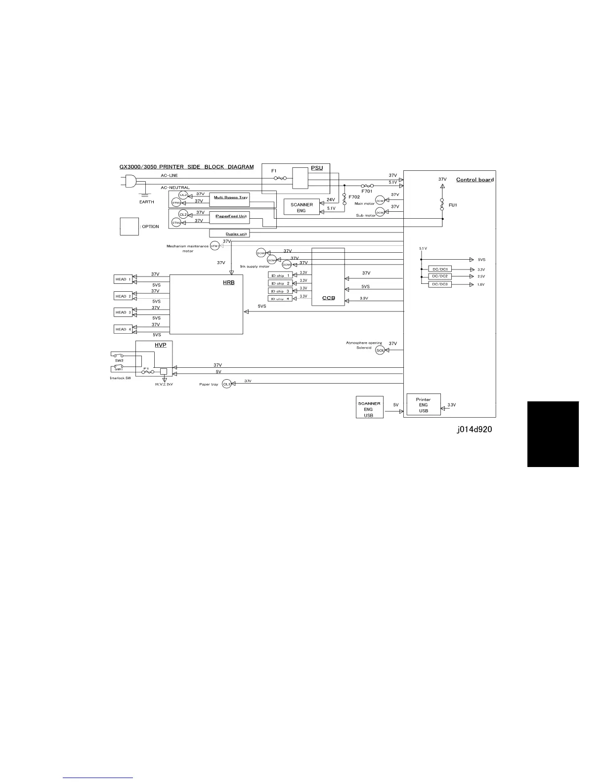
6.2.1 BOARD CIRCUIT DIAGRAM
Control Board (Engine CTL Board). (Engine Controller Board)
The control board exerts overall control of the machine, including
Image data processing
Interface management: USB and all the other boards
Controls all sensors, and motors for all I/O devices
Scanner ENG (CTL Board). (Scanner Controller Board)
Controls the operation of the scanner unit
PSU. (Power Supply Unit). Mounted on the left side of the machine. Supplies power to the
HVPS (HVP), all motors, and the scanner unit.
CCB. (Cartridge Control Board). Mounted in the cartridge holder behind the right front door
of the printer. This PCB relays signals between the control board on top of the printer and
the ink pump motors that supply ink to the ink tanks. It also relays the ID chip signals that
detect whether the ink cartridges are installed properly in the correct slots of the cartridge
holder.
 Loading...