7. OPERATING ADDITIONAL FUNCTIONS
IMR02C15-E4
7-8
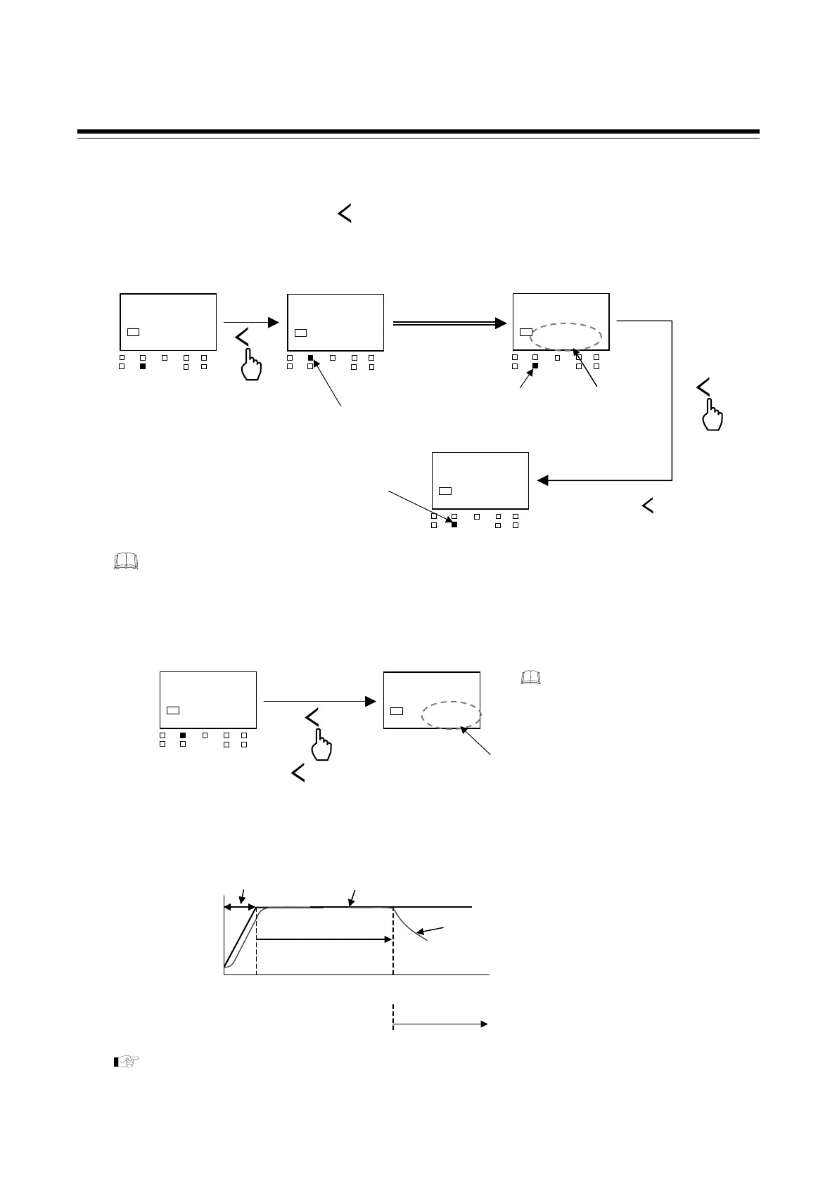
Timer start
When the settings for the Timer function 2 are finished, start the timer.
In the STOP state, press and hold the key for 2 seconds or more to switch to RUN (control RUN).
The timer starts, and when the set timer time elapses, the state changes to STOP and control is
stopped.
In addition to starting the timer by front key operation, digital input (DI) [optional] or
communication [optional] can also be used to start the timer at transfer from STOP to RUN.
• Remaining time monitor
While timer time is elapsing, the remaining timer time can be monitored.
• Timer operation when Setting change rate limiter (up) is enabled
When the Setting change rate limiter (up) parameter is enabled, timer operation starts when Setting
change rate limiter operation ends.
For the procedure for enabling Setting change rate limiter (up), refer to • Ramping the set
value (SV) in Control start (RUN) by Timer function (Timer function 1) (P. 7-6).
R/S
Power ON or STOP → RUN
Control is started (PV start) at
Measured value (PV) = Set value (SV)
Measured value (PV)
Timer time
Control stop (STOP)
Set value (SV)
STOP lamp flashing
Setting change rate limiter operates
2 seconds
or more
150
TSTP
SV1
OUT1
OUT
T
DO1 DO
MAN
STOP
D
3
DO4
PV/SV monitor
(STOP state at timer end)
STOP lamp flashing
28
STOP
SV1
OUT1
OUT
T
DO1 DO
MAN
STOP
DO3
DO4
PV/SV monitor (STOP state)
2 seconds or more
R/S
PV/SV monitor (RUN state)
28
150
SV1
OUT1
OUT
T
DO1 DO
MAN
STOP
DO3
DO4
STOP characters
are displayed
when timer ends
Output (OUT1) lamp lights
28
STOP
SV1
OUT1
OUT
T
DO1 DO
MAN
STOP
DO3
DO4
STOP lamp stops flashing
and lights steadily
R/S
PV/SV monitor (STOP state)
In the STOP state due to timer end,
ress and hold the key for 2
seconds or more to switch to the
STOP state for the next RUN
R/S
While timer time
is ela
sin
The Remaining time monitor is not
displayed if the Monitor selection
(no display) (
ModE) parameter is
set to “8” in Engineering mode
F00.
PV/SV monitor (While timer time is elapsing)
120
150
SV1
OUT1
OUT
T
DO1 DO
MAN
STOP
DO3
DO4
Displays the Remaining time
of the timer.
TIME
8:35
SV1
R/S
Remaining time monitor
Press the key to Remaining
time monitor screen (
TIME)
R/S

 Loading...


