164 Rockwell Automation Publication IASIMP-QS005H-EN-P - April 2016
Chapter 6 Safety System Application Guide
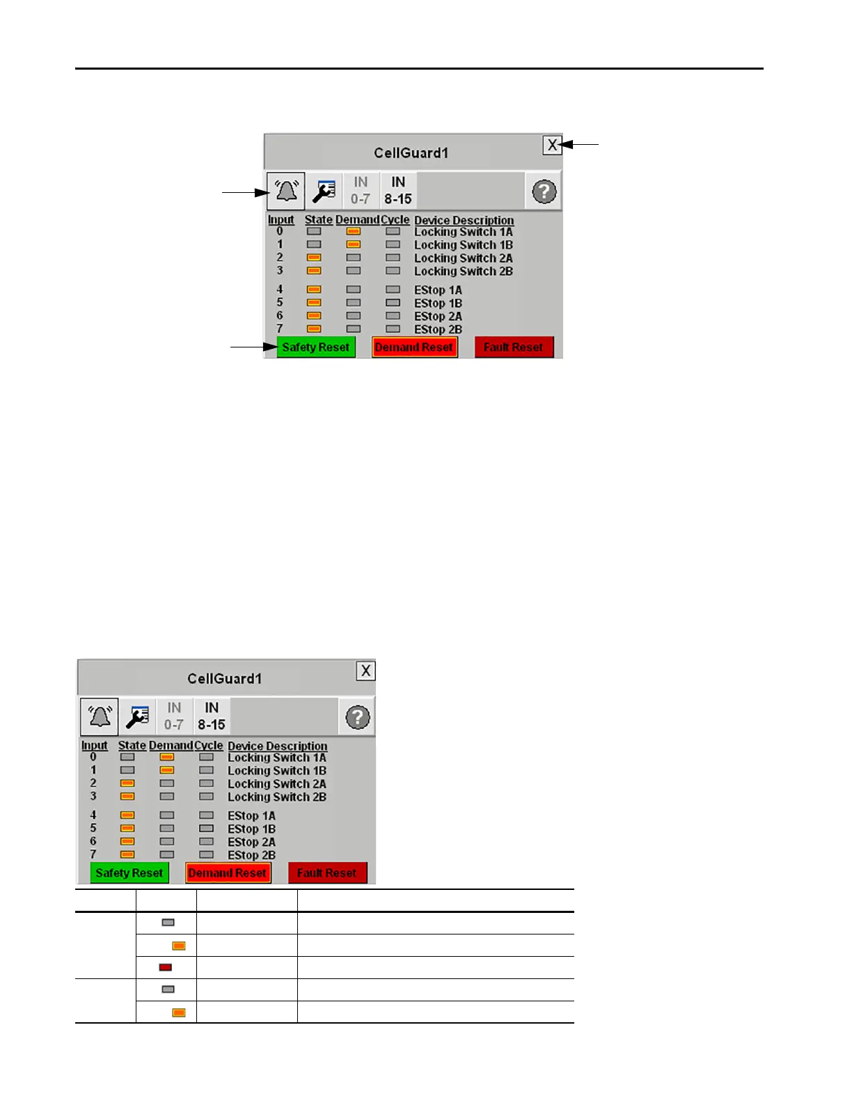
Digital Guard I/O Module Faceplate Overview
The faceplate toolbar includes these buttons:
•The Alarm button indicates a Guard I/O module fault condition and activates the Error Content view. A black
bell indicates normal status, with no faults. A yellow-black flashing bell indicates a fault condition.
•The Configuration button lets you edit the Guard I/O faceplate name or Device Descriptions.
•The Input/Output Selector buttons let you select which view is shown.
•The Help button let you select Help information for the view.
To close the faceplate, click the Close button in the upper right corner of the display.
Digital Guard I/O Module Faceplate Input Status View – Demand Indication
This Guard I/O faceplate view illustrates a 16-point Guard I/O module’s 0…7 input channel status. The IN 0-7 button is
lighter to confirm this view. The faceplate provides State, Demand, and Cycle indication for each input.
Faceplate Toolbar
Status Indicators
Command Buttons
Close
{
Indicator Color Description Action Required
State Gray De-energized (OFF) None
Orange Energized (ON) None
Red Faulted Clear the Input/Output (device) fault.
Demand Gray No Demand on input None
Orange Input in Demand
(1)
(1) A high-to-low transition of the input causes a demand.
Set inputs (devices) to active state, if necessary. Press Demand Reset.
 Loading...