Rockwell Automation Publication IASIMP-QS005H-EN-P - April 2016 113
SmartGuard™ 600 Controllers Logic Integration Chapter 4
Configure SmartGuard 600 Local Outputs
The SmartGuard 600 local output configuration is dependent on the output device type, output relationship, and fault
detection requirements. All of the outputs are pre-configured for coil devices to perform the diagnostics necessary to
achieve the safety category level indicated by the pre-configured .dnt file name. Use the following steps and table
recommendations to configure the safety outputs.
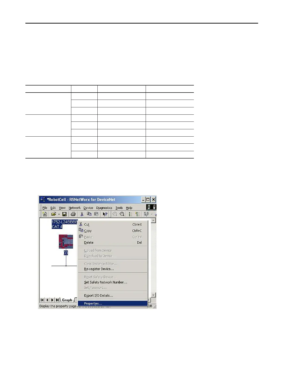
1. To access SmartGuard 600 local output properties, right-click the SmartGuard controller and choose Properties.
Table 11 - Typical Safety Output Configuration Parameters
Output Device Type Category Channel Mode Dual Channel Mode
Coil 4 Safety Pulse Test Dual Channel
3Safety Dual Channel
2 Safety Pulse Test Single Channel
Solid-state actuators
(non-reactive to pulse testing)
4
(2)
(2) Must be a Category 4 capable device.
Safety Pulse Test Dual Channel
3
(3)
(3) Must be a Category 3 capable device.
Safety Dual Channel
2
(4)
(4) Must be Category 2 capable device.
Safety Pulse Test Single Channel
Solid-state actuators
(reactive to pulse testing)
(1)
(1) For example, Kinetix® 300 or Kinetix 350 drives.
4
(2)
Safety Dual Channel
3
(3)
Safety Dual Channel
2
(4)
Safety Single Channel
 Loading...