Rockwell Automation Publication IASIMP-QS005H-EN-P - April 2016 167
Safety System Application Guide Chapter 6
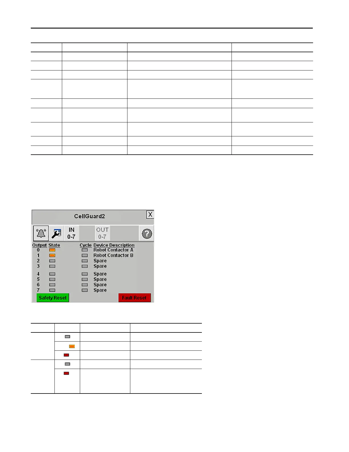
Digital Guard I/O Module Faceplate Output Status View
The Guard I/O Faceplate Output Status view operates identically to the Input Status view except it does not have
Demand associated with it.
The following table provides the indicator descriptions, color codes, and required actions.
Code (hex) Error Content Probable Cause Recommended Action
01 Configuration invalid The configuration is invalid. Configure the module correctly.
02 Over current detected Trouble with the connected device. Replace the connected device.
03 Short-circuit detected Ground fault of the output signal line. Check the wiring.
04 Output ON error 1. The power source (positive side) is in contact with the output
signal line.
2. Trouble with the internal circuit.
1. Check the wiring.
2. Replace the module.
05 Error in the other dual channel output Dual channels are set and an error occurred in the other channel. Remove the error in the other channel.
06 Internal-relay output circuit error Trouble with the internal circuit (1791DS-IB4XOW4 module
only).
Replace the module.
07 Relay error Trouble with the relay
(1791DS-IB4XOW4 module only).
Replace the relay.
08 Output data error Wrong setting for output data. Check the program.
09 Short-circuit detected in output Short-circuit between output signal lines. Check the wiring.
Indicator Color Description Action Required
State Gray De-energized (OFF) None
Orange Energized (ON) None
Red Faulted Clear the Input/Output
(device) fault.
Cycle Gray Input/Output not faulted. None
Red Input/Output faulted. Clear the Input/Output
(device) fault.
Cycle Input/Output.
Press Fault Reset.
Press Safety Reset.
 Loading...