94 Rockwell Automation Publication IASIMP-QS005H-EN-P - April 2016
Chapter 3 GuardLogix® Controllers Logic Integration
Map Digital and Analog GuardIO_AOI Tags to Safety Zone Reset Tags
You must create ladder logic to map Digital and Analog GuardIO_AOI module reset tags to controller safety tags. This
enables the faceplate reset buttons to execute safety and fault resets.
1. Add a rung directly after your last Digital or Analog GuardIO_AOI instance rung for each of your safety zones.
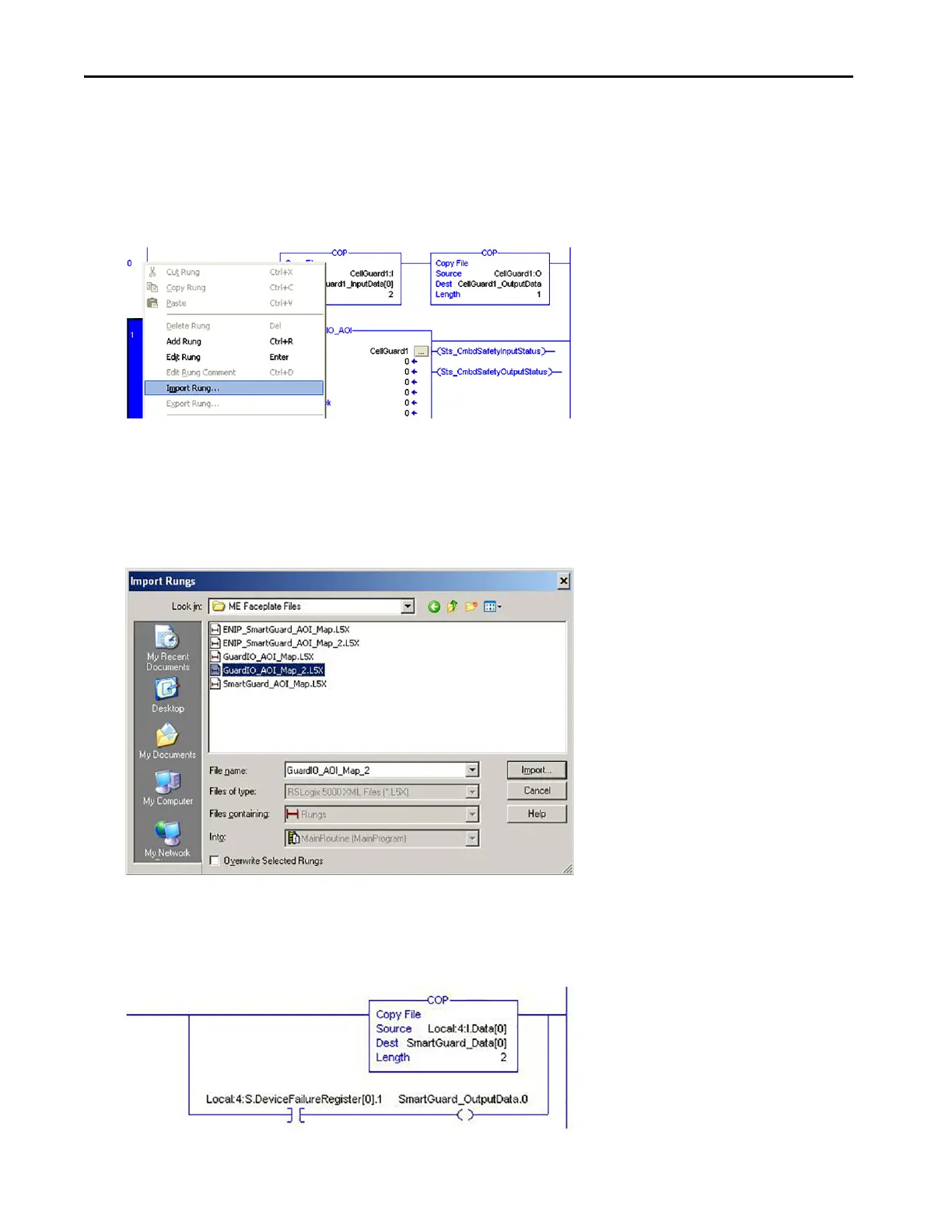
2. Right-click your last Digital or Analog GuardIO_AOI instance rung and choose Import Rung.
3. Browse to the ME Faceplate files folder within the Guard I/O and SmartGuard Faceplate Files toolkit directory.
If the toolkit has been loaded onto your personal computer, the hard drive path is C:\Program Files\
RA_Simplification\SafetyGuardLogix\Files\Guard IO an
d SmartGuard Faceplate Files\ME Faceplate Files.
4. Select the GuardIO_AOI_Map_2 file and click Import.
Alternatively, if the safety I/O module you are configur
ing is a SmartGuard 600 controller (1752-L24BBB), then
import SmartGuard_AOI_Map instead of the GuardIO_AOI_Map_2.
You must also set the copy instruction source tag to the corresponding SmartGuard 600 mapping in the 1756-DNB
module and set the DeviceFailureRegister bit to correspond with the SmartGuard DeviceNet node as shown here.
 Loading...