82 Rockwell Automation Publication IASIMP-QS005H-EN-P - April 2016
Chapter 3 GuardLogix® Controllers Logic Integration
Refer to these manuals for additional diagnostic information that is available from Guard I/O Modules:
• Guard I/O DeviceNet Safety Modules User Manual, publication 1791DS-UM001
• Guard I/O EtherNet/IP Safety Modules User Manual, publication 1791ES-UM001
• POINT Guard I/O Safety Modules User Manual, publication 1734-UM013
17. Repeat the Configure Guard I/O Module Add-On Instruction Message Instructions for each Digital Guard I/O
Faceplate steps 1…16, on pages 78…81 for each of the GuardIO_AOI instructions in your application.
See Appendix
A for the completed faceplate logic for the Robot Cell Module and Safety Zone Configuration used in this
toolkit.
Faceplate Logic for Analog Guard I/O Faceplates
Import Add-On Instructions for Analog Guard I/O Faceplates
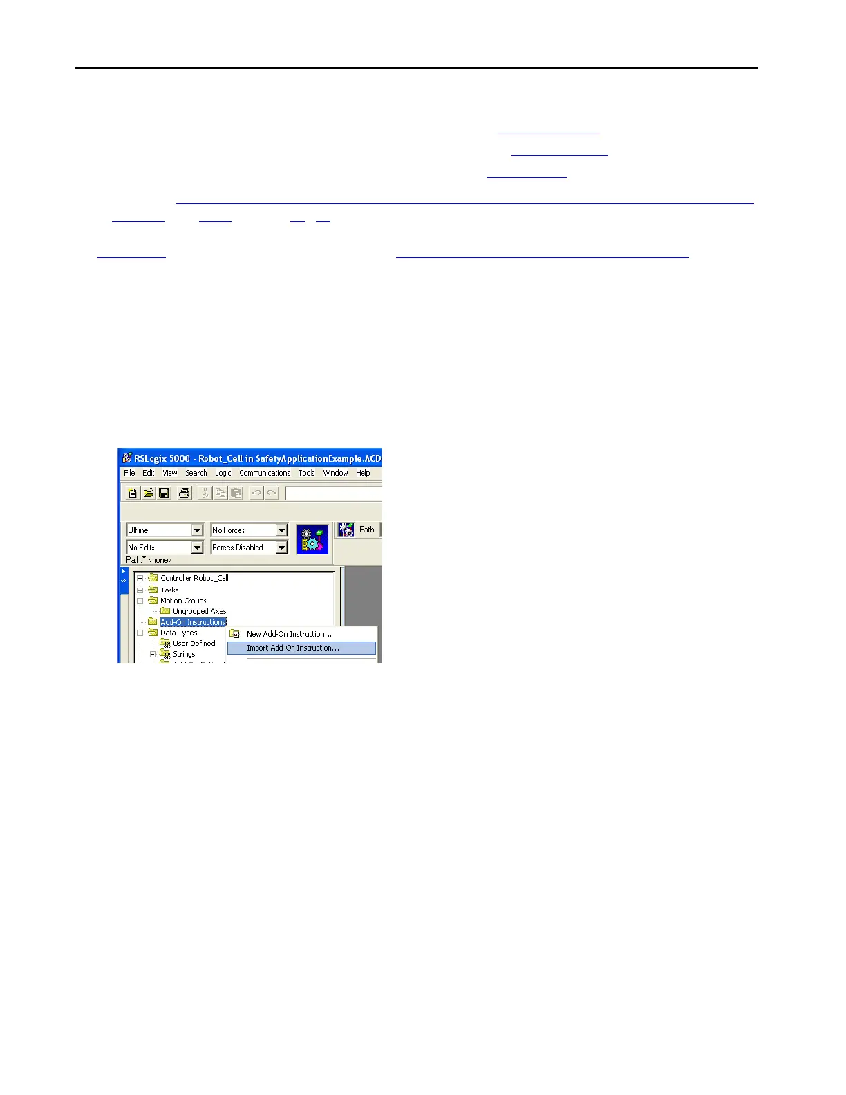
1. In your RSLogix 5000 application file, right-click Add-On Instructions and choose Import Add-On Instruction.
2. Browse to the ME Faceplate Files folder within the Guard I/O and SmartGuard Faceplate Files directory in the
toolkit.
If the toolkit has been loaded onto your personal computer, the hard drive path is:
C:\Program Files\RA_Simplification\SafetyGuardLogix\Files
\G
uard IO and SmartGuard Faceplate Files\ME
Faceplate Files.
 Loading...