Rockwell Automation Publication ICSTT-RM448M-EN-P - February 2021 57
Chapter 4 Before You Begin
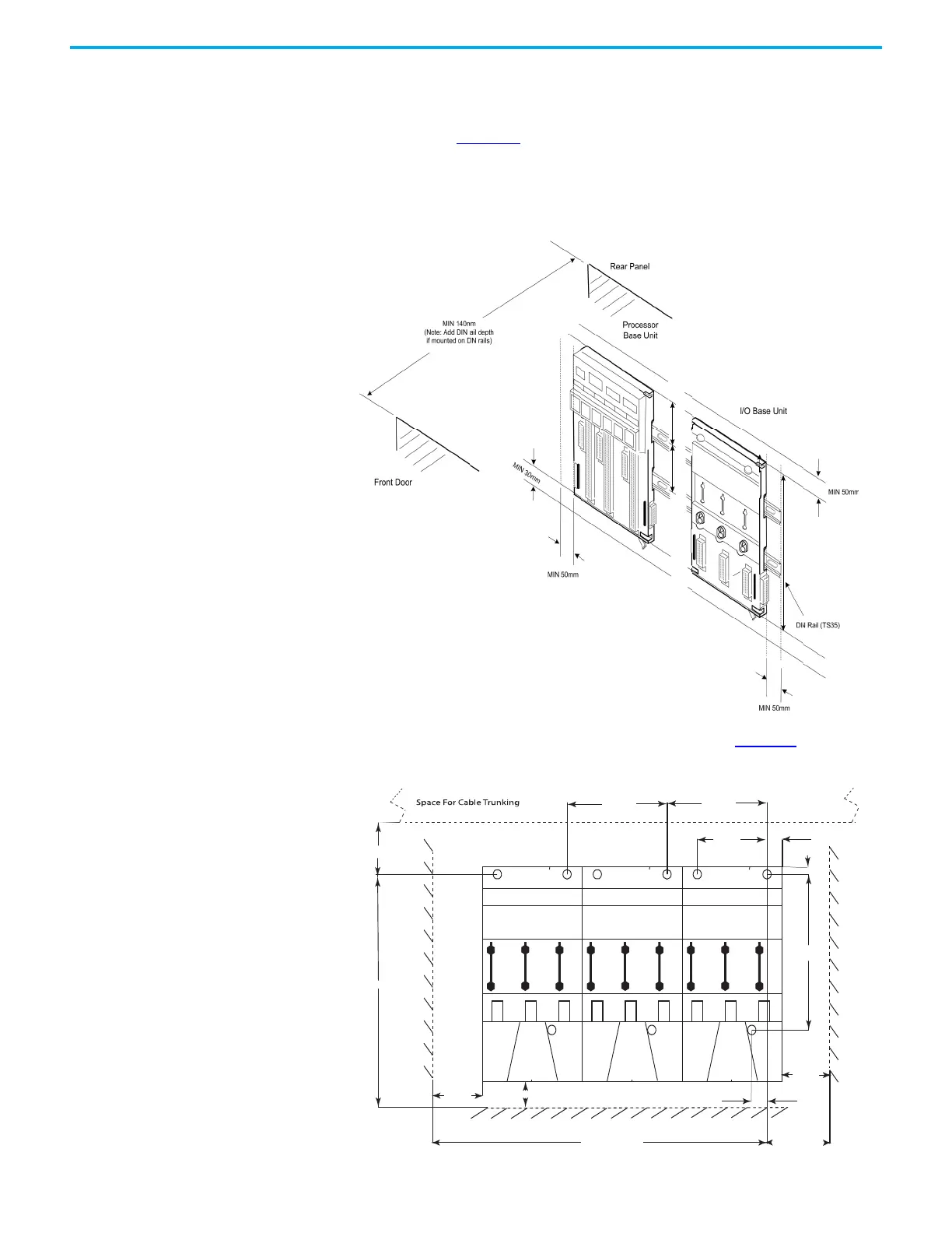
If an expansion cable is to connect to the left-most base unit, the controller also
needs space to the left, to fit the expansion cable adapter.
This illustration (Figure 10
) shows the minimum recommended clearances
and rail positions for DIN rail mounting. The clearances also apply to flat panel
mounting.
Figure 10 - Free Space for Din Rails Fitting
The flat panel drilling holes are shown in the illustration (Figure 11) below:
Figure 11 - Flat Panel Mounting
233mm
Each base unit (2 shown)
occupies 126mm width.
101mm 46mm
19 mm
19 mm
88 mm
126 mm
126 mm
HOLE ‘A’
DIMENSION ‘X’
7 mm
Minimum
Clearance
50 mm
Minimum Clearance
30 mm
Minimum
Clearance
50 mm
MIN 69 mm

 Loading...


